- Introduction
- Donor Information
- Workflow
- Disassembly
- Oil Pan (ORS-EC089, EC090, EC091, EC092, EC092)
- Engine Preparation
- Exhaust
- Transmission Prep, When Using Donor Transmission
- Frame Mounts
- Battery Mounting
- Clutch Install, Transmission (ORS-EC058, MAR-MCCL-119, ORS-EC068 – CLUTCH)
- Engine Install
- Shifter Installation – IF Using Donor A340F/E Automatic Transmission
- Under-Hood Assembly
- Exhaust System
- Conversion Wiring Install (ORS-EC020, ECO21, EC022, EC023, EC024, EC025, EC026, EC029)
- Under-Hood Completion
- Instruction Supplements
- Wiring Supplements
- Wiring Supplements, for Various Auto-Transmission Applications
- For ADAPTER Harness ONLY – ’89-’95 4×4 Trucks/’90-’95 4Runner Using 3.0L A340H A/T and Transfer Case
- For ADAPTER Harness ONLY – ’85-’88 4×4 Trucks/’85-’89 4Runner Using A340H A/T and Transfer Case
- Automatic Transmission Applications When Using DONOR Floor Shifter
- When Installing 5VZ/3RZ A/T Into A43D Vehicles OR Originally M/T Vehicles
- General Supplements
Introduction
Read and fully understand this entire guide BEFORE starting work. This installation and any problems occurred within are the sole responsibility of the installer. We strongly recommend that you acquire all the necessary parts and tools before starting this project.
While this guide is intended to be informative, it is not intended to a step-by-step instruction set. Some swaps may require deviation from this guide due to circumstances or other modifications. The details and install procedure for any engine swap is the sole responsibility of the installer.
This guide is also intended to be an install guide for any related Off Road Solutions 5VZ 3.4L Conversion Product. Therefore, each section is written as an install guide for the related ORS product. This also means that not all sections in this guide will pertain to every conversion.
This install guide is written with a 1979-1995 Toyota Truck/4Runner in mind, but much of the process would still apply to other vehicles.
-
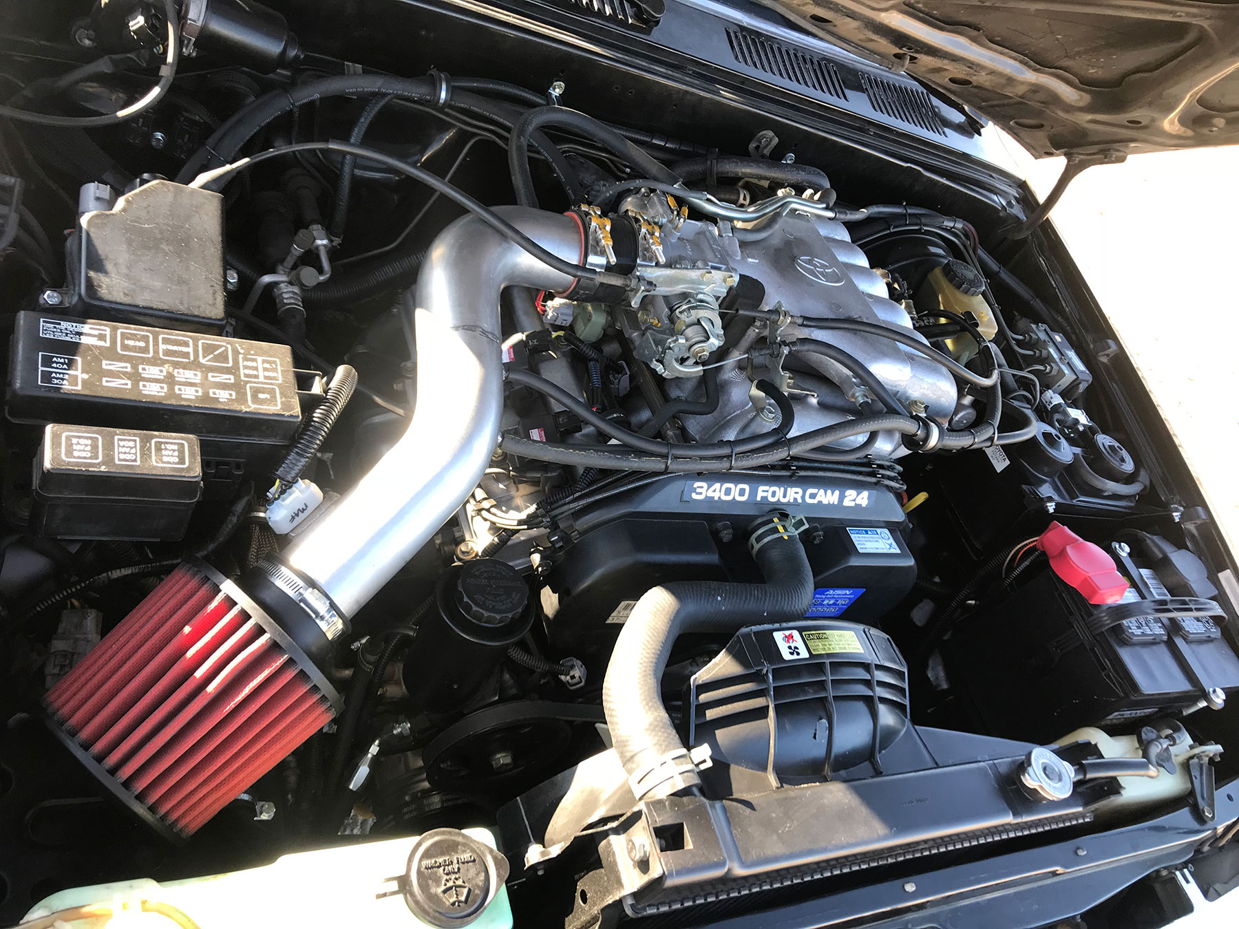
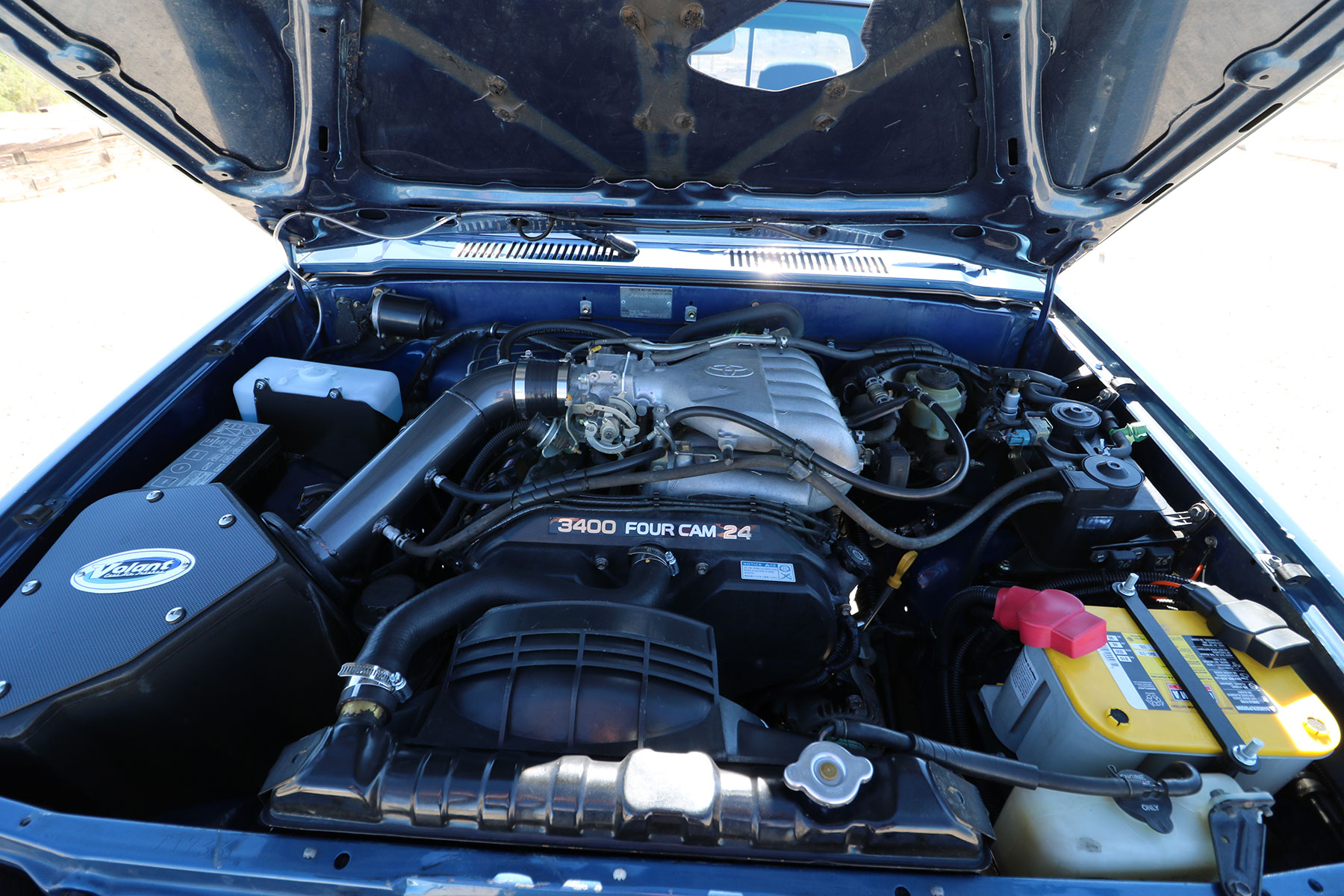
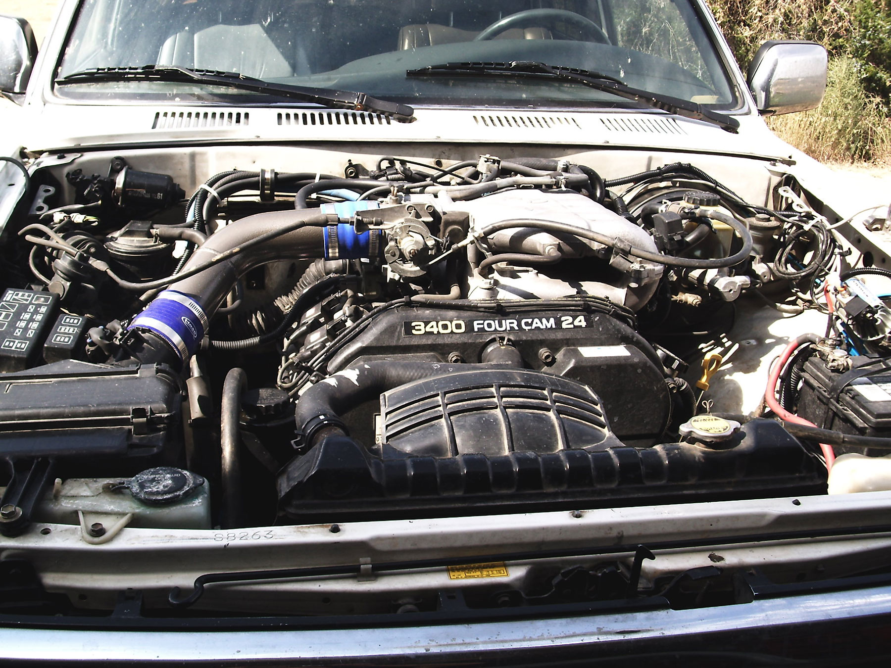
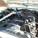
- Completed Swap
-
- Completed Swap
-
- Completed Swap
Here are some acronyms and name variations that you will find in this document:
- 5VZ-FE, 5VZ and 3.4L all refer to the Toyota 5VZ-FE 3.4L V6 engine featured in this conversion
- ECU is a term used to describe the engine control computer, some people refer to this as an ECM
- swap and conversion are both used to describe the engine conversion process
- 3VZ-E, 3VZ and 3.0L all refer to the Toyota 3.0L V6 engine which is often removed before this conversion
- When referring to bolt size, the thread size will be used. For example, when referring to a 6mm bolt, the thread is 6mm and the hex size is normally a 10mm.
- ORS = Off Road Solutions
- Donor vehicle – the 5VZ donor vehicle (or application)
- Recipient vehicle – the vehicle receiving the engine
- LH & RH – this will refer to the side of the vehicle when sitting in the driver seat; LH is driver-side for US-based vehicles
- A/T & M/T – this refers to Automatic-Transmission and Manual-Transmission
- B1S1 & B1S2 – this refers to Bank1 Sensor1 & Bank1 Sensor2, a term used for O2 sensors. B1S1 is placed upstream of catalytic converter(s) and B1S2 is placed downstream of catalytic converter(s).
When preparing for this conversion, there are a few groups of parts to consider.
- Donor Parts – The engine itself and the OEM parts associated with it. These parts are often found in a salvage yard. Another way to obtain the donor parts is to purchase a complete vehicle (normally wrecked) with a 3.4L 5VZ-FE engine.
- Conversion Parts – Parts that cannot be found on the donor or recipient vehicles. Some conversion parts (whether purchased or built) are required to complete the swap. Some may not be required, but make the conversion easier or cleaner. ORS offers many conversion parts and kits to aid in the 3.4L engine conversion. See our application guide, in the ‘tech info’ section of our website to determine which conversion parts are right for your application.
- Service/Repair Parts – When doing this conversion it is a good idea to replace simple service/repair parts that need attention. These parts may include spark plugs, drive belts, filters, timing belt, seals, etc. Many of these parts are available through ORS.
- Exhaust Parts – The recommended diameter for exhaust on this engine is 2.5”; 2.25” also works well. If using any part of the original exhaust, be sure the diameter is no smaller than 2.25” in any place. If building a new exhaust, parts needed will include:
- Catalytic converter(s), Muffler, Flex Coupler, Tubing material (bends if needed), flange(s) w/ gasket(s) or coupler(s), O2 sensor bungs, hangars w/ insulators, etc.
Donor Information
Donor Parts
This is a list of the OEM parts required from a 3.4L 5VZ-FE equipped vehicle. These are normally used parts. If parts are purchased through a salvage yard, we recommend purchasing this entire list as a ‘package’ deal from the same vehicle. Many of the parts listed below are normally on the engine.
- 5VZ-FE long-block; new, remanufactured, or used
- Both exhaust manifolds (unless using a header system)
- Intake manifold
- Intake plenum with throttle body
- All items on engine related to fuel injection such as injectors, fuel rail, VSV’s, sensors, throttle body, etc.
- Alternator and brackets
- Power steering pump and brackets
- A/C compressor and bracket (optional)
- Spark plugs
- Spark plug wire set
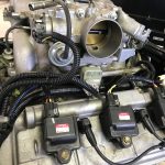
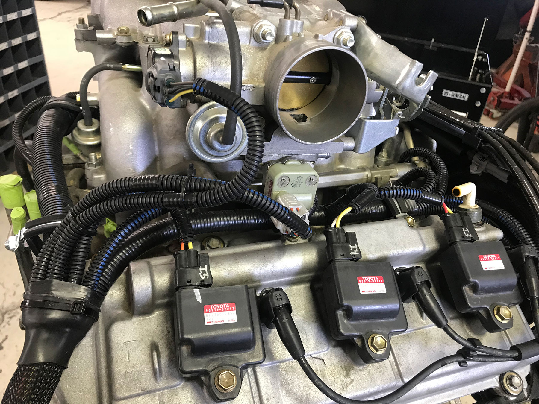
- Cylinder coil packs (3)
- Radiator fan and clutch (3.0L version may work)
- Battery cable harness
- Engine (injector) wiring harness
- ECU (engine computer)
- Igniter assembly (flat, square shape, near intake box)
- Intake system- tubing, air box, air filter. If upgrading to an aftermarket intake system, only the air flow meter and hardware will be necessary.
- Air flow meter
- Evaporative canister (optional)
- Evaporative vapor pressure sensor
- Evaporative vapor pressure VSV
- Evaporative purge VSV
- Starter (3VZ-E starter can also be used)
- Flywheel with mounting hardware (unless using 3VZ-E flywheel) M/T
- Oxygen sensors (2), one on each end of catalytic converter
- OEM oxygen sensor exhaust bungs (welded to pipe) – new weld-in bungs available
- All the OEM hardware you can get your hands on…
- Automatic transmission assembly w/ torque converter (optional) A/T **
- Shifter assembly (optional) A/T **
- Transmission cooler hard lines (optional) A/T **
- Transmission lower inspection cover (optional) A/T **
- Drive plate and mounting hardware (optional) A/T **
- Torque converter x drive plate mounting bolts (optional) A/T **
- Gear driven transfer case – 23 spline, top shifting configuration (4×4, optional) A/T **
**Items only needed for A/T applications where the donor 5VZ A340F/E transmission is used
The following parts are required from a 3.0L 3VZ-E application:
- Radiator, preferably ‘89-’95 Truck, ’90-’95 4Runner
- Fan Shroud
- Radiator Fan (3.4L fan is preferred)
- 3.0L fan clutch assembly (3.4L clutch will also work)
- Engine Mount Brackets, if using OEM style mounts, preferably ’91-’95 Truck/4Runner
- OEM hardware for transmission and engine mounting
- Oil pressure sending unit (if equipped with oil pressure gauge), 22R application also OK
Donor Application Information
It is very convenient when all 3.4L donor parts come from the same vehicle. However, this is often not possible. When searching for donor parts from various sources, here are some general application differences that may be encountered:
- JDM-sourced engines: JDM refers to Japanese Domestic Market. These engines are often found online or on Ebay. These are salvage engines from vehicles bought and operated in Japan. These JDM engines can be used but have several external differences to consider when doing a swap. See this link if using a JDM engine.
- *1995-1996 Tacoma and T100 models use a 4-wire throttle position sensor (TPS), while all other models use a 3-wire TPS. Unfortunately the two TPS types require a different throttle body, so changing from one type to another requires changing the entire throttle body. If using a 4-wire TPS in a 3-wire system, removing the proper wire at the connector will still allow the use of the 4-wire TPS.
- *1998 and earlier air flow meters are larger and are part of the air intake tube. 1999 and newer air flow meters are much smaller and mount to the side of the intake tube with 2 screws. Both share the same electrical connectors but will cause very poor drive-ability with the wrong engine harness. The cure to this problem is a simple re-pin at the connector; see the supplement at the end of these instructions.
- *2001 and later models, 1999-2000 4Runner California, and 2000 Tacoma/Tundra California models use an ‘Air/Fuel Sensor’ in place of the upstream (pre-converter) oxygen sensor. While these sensors are identical in appearance, they are not compatible. These newer models will also require 2 catalytic converters, installed in series.
- 2001-2002 4Runner and 2002-2004 Tacoma and 2003-2004 Tundra models use an EVAP canister that is mounted under the vehicle, near the fuel tank. In this case (with the exception of strict emission testing), it is simpler to use an under-hood canister and parts from a 1996-2000 4Runner or 1997-2001 Tacoma.
- 2001-2002 4Runner and most 2003-2004 Tacoma/Tundra models were equipped with an Electronic Throttle Control System (ETCS), also known as ‘drive-by-wire’. This 5VZ system is all contained in the throttle body and still uses a traditional throttle cable. While this system also works well in a conversion, the engine harness and ECUs are different than other models. This will also have an effect on how Cruise Control can be utilized.
If using an Adapter Harness it is important that the ECU and the wiring harness are compatible. There are many variations of these parts through the models and years, and they are not all interchangeable. If these parts cannot be located from the same vehicle, ORS can provide application recommendations.
New/rebuilt parts are ideal, however, used parts are most commonly used. Remember that used parts are always a gamble. No matter the situation, there is always a risk that a used part may fail prematurely. A salvage yard will often warranty a failed part with a used replacement; within a given time. A labor warranty from a salvage yard is almost unheard of. We highly recommend a compression test of the engine. Any background information may also be useful, such as the nature of the wreck that put the donor vehicle into the salvage yard or even service records.
Note: A V6 (R150), turbo 4-cylinder (R151), or A340 transmission is required for use with the 3.4L engine. The W and G-series transmissions are not strong enough to withstand the 5VZ power output long-term.
Workflow
The workflow outline shown below is a good general guideline. However, some swaps will have unique circumstances or parts. This outline is only a guide.
- Removal of the original engine and related parts.
- Removal of necessary parts from original engine (oil sender, mount brackets, oil pan, etc.)
- Any necessary repair/service needed on 5VZ engine
- Install oil pan kit and related parts on new engine
- Install engine mounts/brackets
- Install banjo fitting on fuel rail, if applicable
- Remove/cut outer adjuster from alternator bracket, for steering shaft clearance
- Make sure all accessories are installed on 5VZ engine
- Install exhaust crossover pipe or header system, if applicable
- Make any modifications necessary to the transmission and transfer case
- Install ORS Engine Conversion Wiring on engine (or used/donor engine wiring)
- Install any frame brackets on frame, for engine mounts (if applicable)
- Install battery relocation tray and fuse box cable extension
- Install battery cables on the engine
- If necessary, install transmission in vehicle
- Install flywheel/clutch (inc. bearings) or be sure A/T drive plate is installed/torqued
- Install engine on frame mounts and secure to transmission
- Modify 5VZ starter, if applicable
- Install starter
- Install clutch slave cylinder and hydraulic hose, if applicable
- Install donor A/T shifter, if applicable
- Install heater hoses
- Install fuel hoses
- Install power steering hoses
- Create, modify or install intake system
- EVAP canister/system and vacuum hose install, inc. brake booster hose
- Build/install exhaust system
- Wiring: Install ORS Adapter wiring OR finish ORS Engine Wiring install
- See supplements for any that apply (at the end of instructions).
- Install radiator, fan/pulley, belts, shroud
- Complete A/C system
- Hood clearance
- Check all hose and wire routing
- Fill engine oil, cooling system, power steering fluid and transmission fluid (if applicable)
- Bleed power steering system
- Start engine and bleed cooling system
- Check for an leaks and monitor engine temperature, oil pressure
Disassembly
- If the A/C compressor will be removed from the vehicle, evacuate the A/C system, per local EPA/government regulations. See A/C section for more details.
- Remove the original engine and related components from your vehicle. This will include vacuum hoses and VSVs (vacuum switching valves), the igniter/coil assembly, intake system, battery, radiator, and cooling hoses, etc. Remove the original engine wiring harness and ECU (computer) with the engine. All other original vehicle wiring will remain in the vehicle.
- Note: if the recipient vehicle is equipped with ADD (automatic differential disconnect, Auto-hubs), the upper two VSVs on the RH inner fender will remain in place.
- If using the original transmission, retain the bell housing x engine block bolts. Also retain the engine mount hardware.
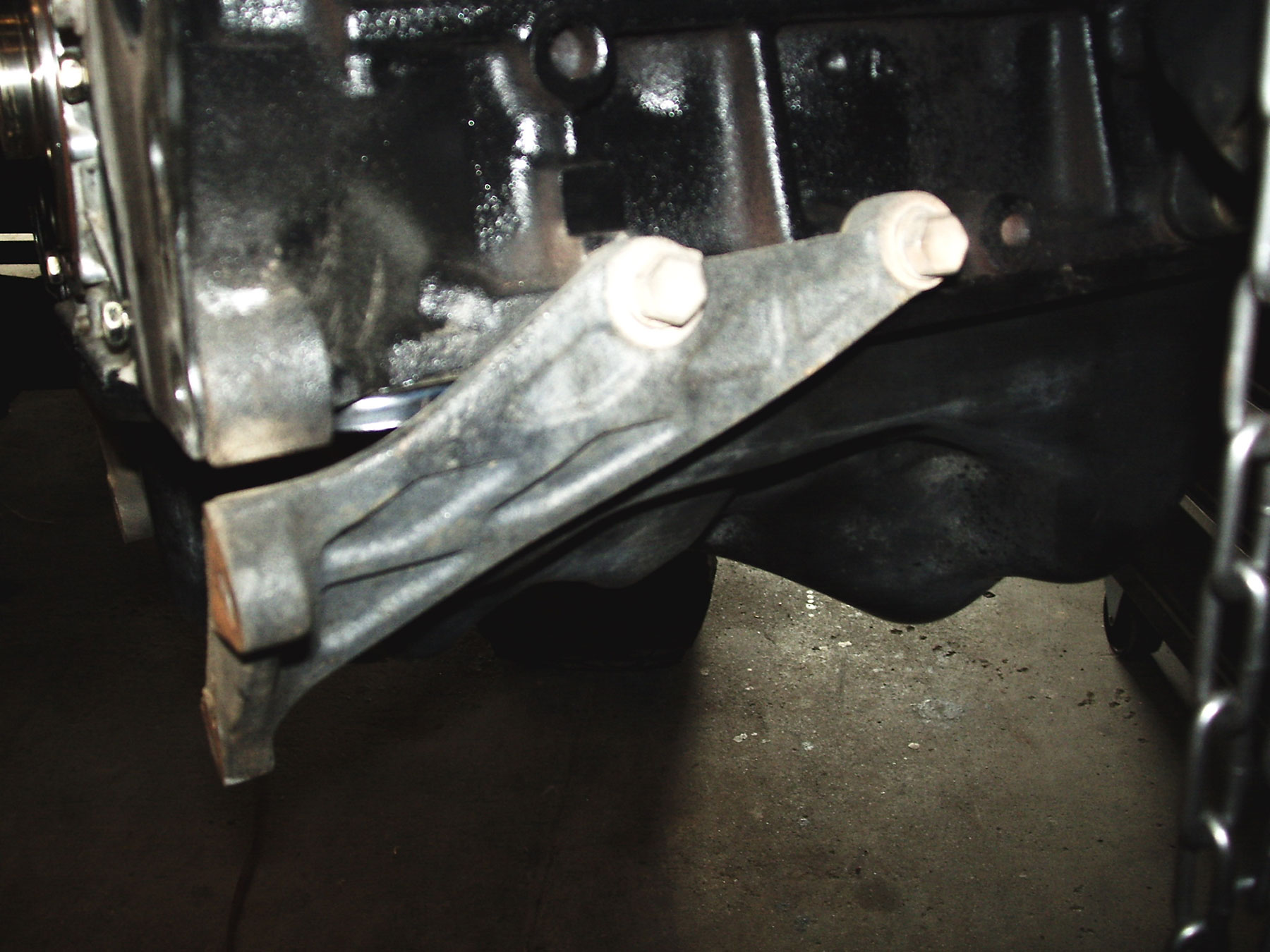
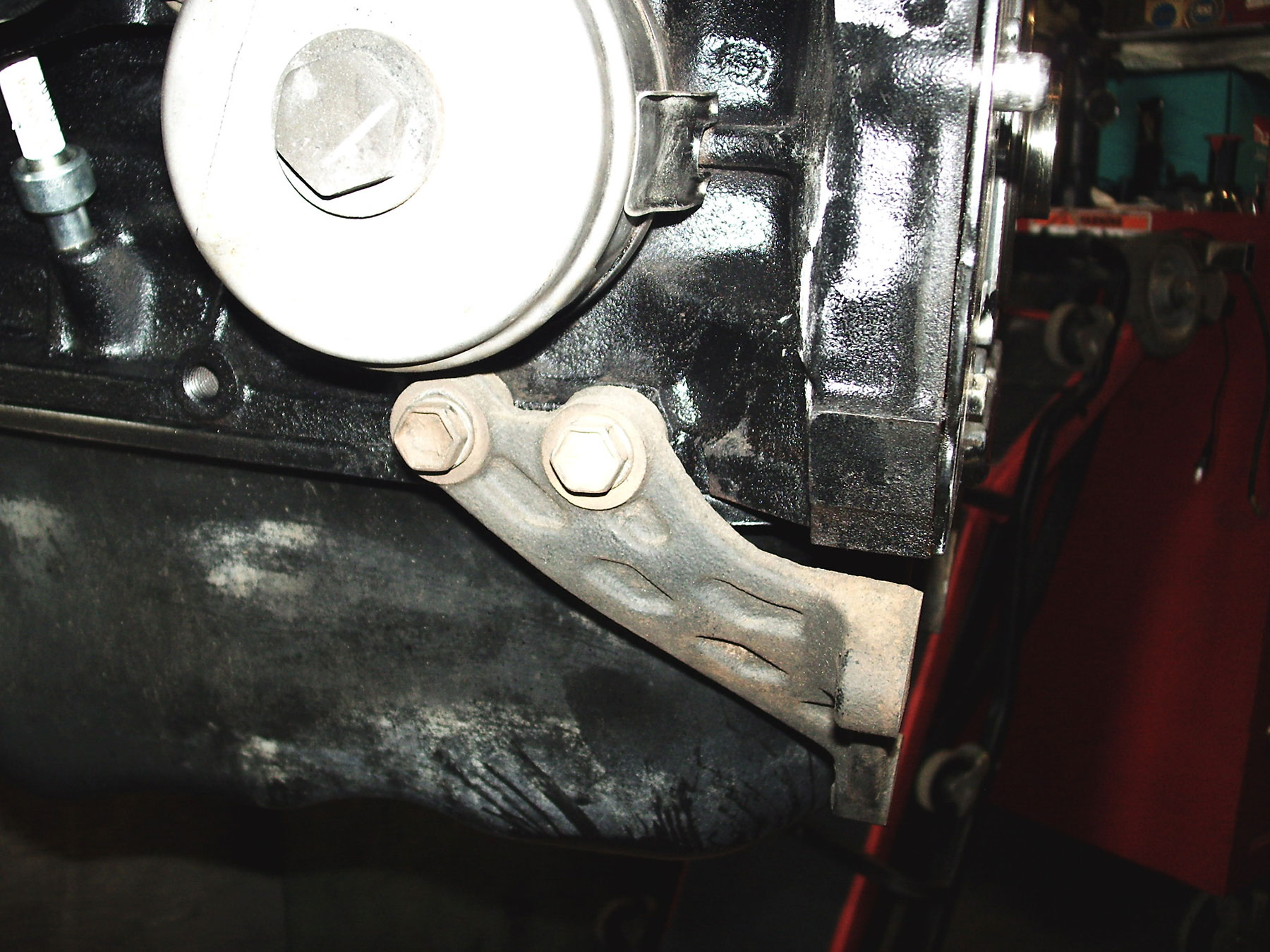
- Remove the stiffening brackets, engine mount assemblies (‘91-‘95 3VZ), and oil sending unit (if an oil gauge is present) from the original engine block and set aside, they will be used later.
- If the original transmission will be used, it can be left in place. If the original transmission is not being used, remove the transmission and related components.
- If using the A/T shifter from a donor transmission: mark the location of the original shifter, in Park, in reference to the interior floorboard.
Preparation
- Securely mount the 3.4L 5VZ engine in an engine stand.
- Remove the engine mounts and brackets from the engine block.
- If any service/repair is necessary on the engine, such as oil leaks, timing belt, this is usually a good time for that.
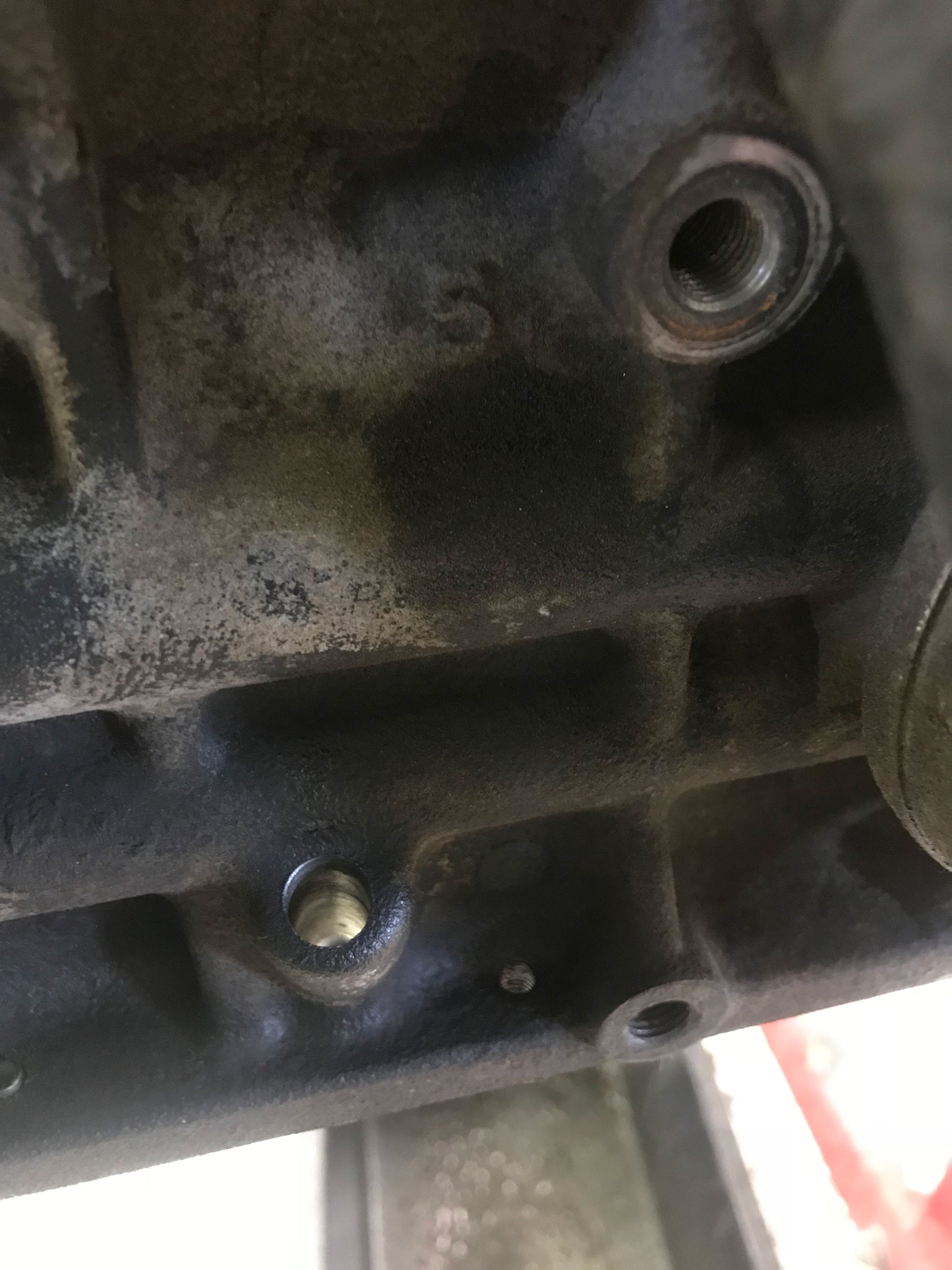
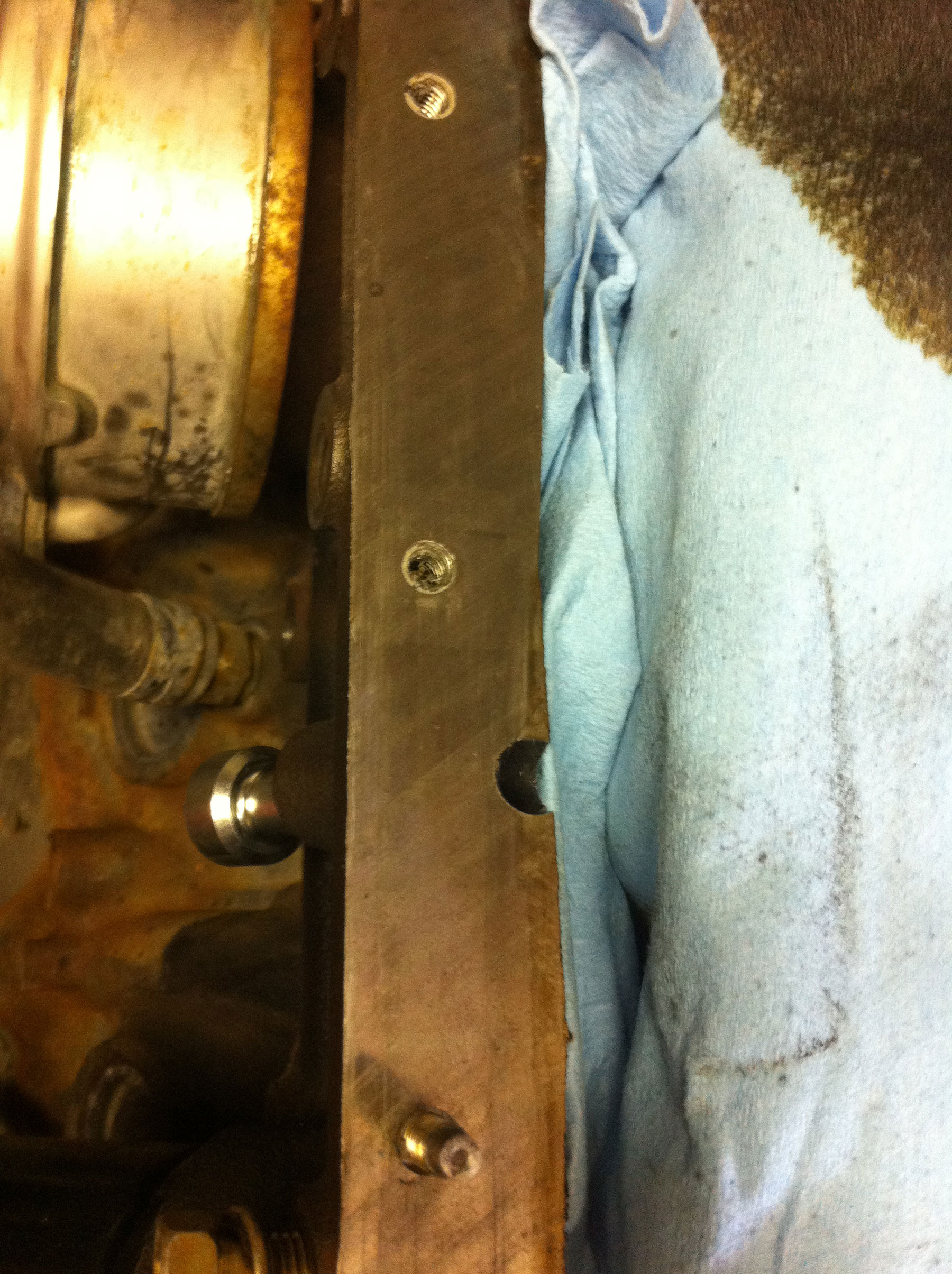
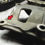
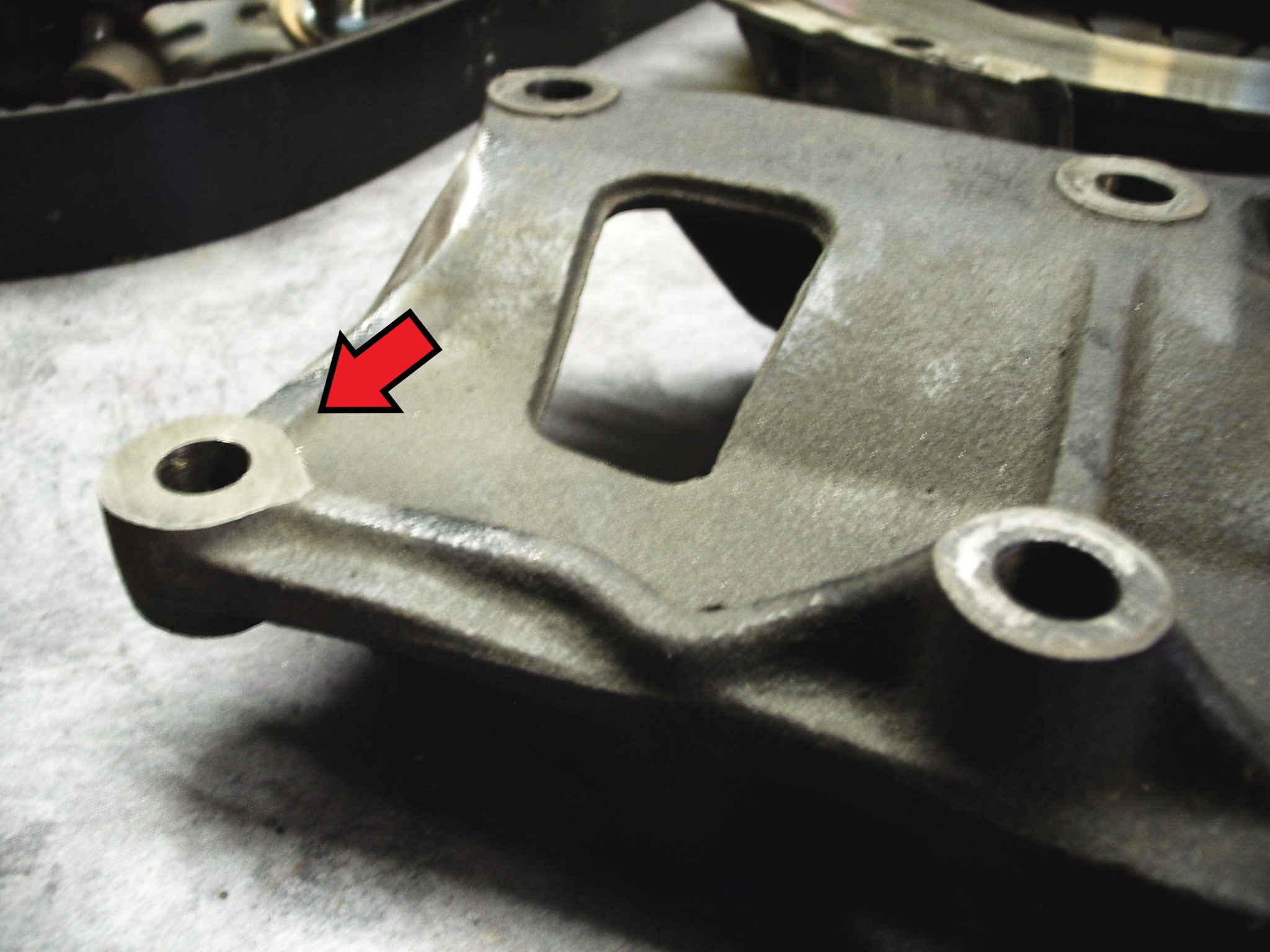
- Prepare for the use of stiffening brackets. Toyota does not use these holes on most 5VZ applications; but they can be used from the 3VZ application for added strength. The holes may need to be tapped, in order to clean the threads. This is a 10mm x 1.25 thread. See pic 0a & 0b.
-
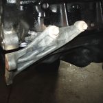
- Pic 0a – Engine stiffening brackets in place
-
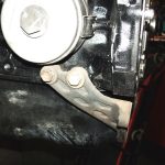
- Pic 0b – Engine stiffening brackets in place
Oil Pan (ORS-EC089, EC090, EC091, EC092, EC092)
- Note: The following steps pertain to Tacoma, 4Runner and Tundra donor vehicles, where the installation of a rear-sump oil pan is required. If the donor vehicle is a T100, the oil pan may not need replacement. See our application guide for details. If switching between a 4×2 and 4×4 T100 oil pan, only the pan and oil sump will be changed.
- With the engine secured upright in the engine stand, drain any oil from the engine. Drain any coolant from the block using the block coolant plug. Remove the oil dipstick and tube from the engine.
- Carefully turn the engine upside down in stand.
- Remove the 6mm bolts securing the pan to the block. Carefully break the sealant bead and remove the oil pan from the engine. Be careful not to score the engine block, rear seal housing, or oil pump housing surfaces.
- Turn the engine upright once again.
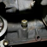
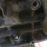
- Using the provided ¼” X 18 NPT size tap, thread the hole in the oil pump housing that the original dipstick tube came from. It may be necessary to first drill this hole, using a 7/16” drill bit. Be sure to thread the hole from the outside of the engine. CAUTION: Take precautions to keep ALL metal particles out of engine. As an alternative, a small freeze plug may be used. This can be pressed into the original dipstick hole in the oil pump, as an alternative to the threaded pipe plug. No drilling or tapping would be necessary with the freeze plug.
- Install the provided ¼” pipe plug in the newly tapped hole, from the outside of the engine. See Picture #1 & 1A
-
- Pic 1 – Oil dipstick plug installed
-
- Pic 1a – Freeze plug installed, alternative to threaded plug
-
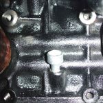
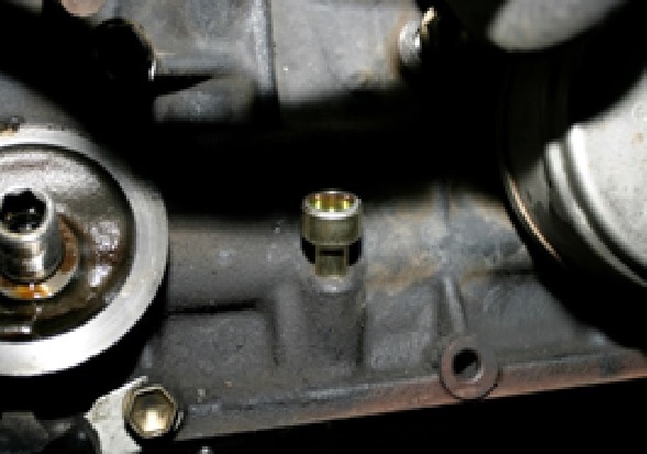
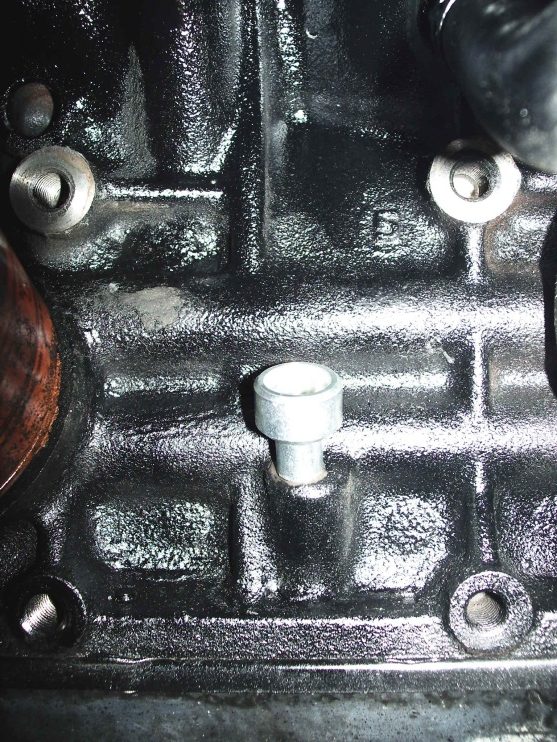
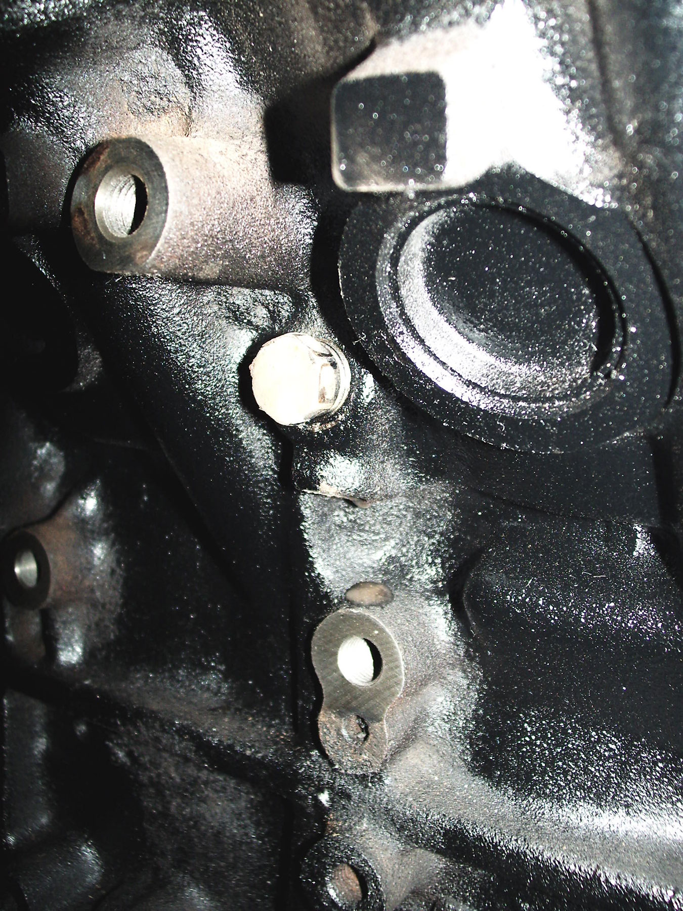
- If the auxiliary oil dipstick hole exists for the new dipstick (see illustration), carefully drive the original plug from the block, this is done from the under-side of engine using a punch and hammer. This hole exists on 1999 and earlier 5VZ-FE engine blocks. See Pic #2
-
- Pic 2 – Factory-installed dipstick hole plug
-
- Tighten all hardware. See Pic #3
-
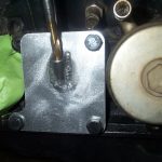
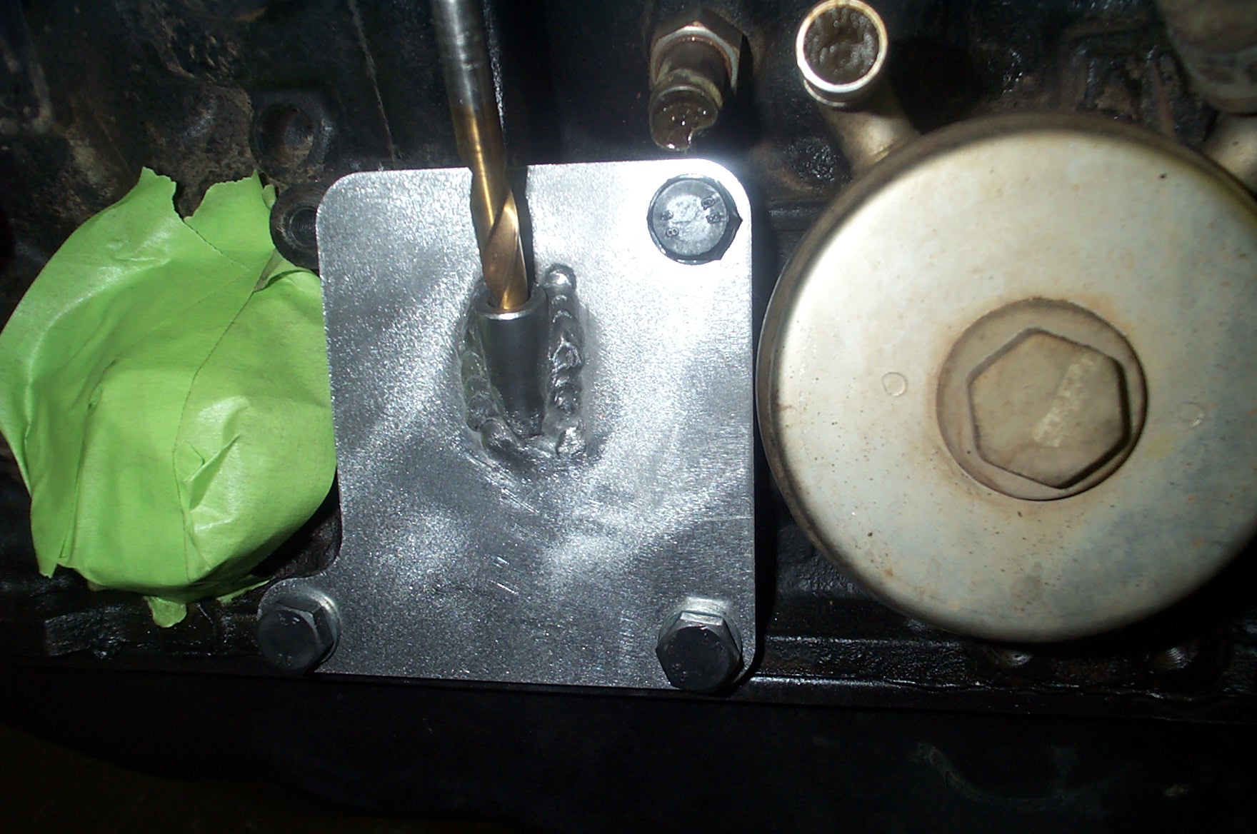
- Pic 3 – Dipstick Drill Guide installed
-
- Insert a U-size (or 3/8” if U not available) drill bit into the guide tube and drill a hole completely through the engine block. The U size will help to ensure a tight fit of the new adapter, but 3/8” is close. NOTE: this hole was not perfectly centered from the factory, nor will our drill guide perfectly center the hole on this landing. See pictures #4, 5 & 6
-
- Pic 4 – Hole properly drilled in block
-
- Pic 5 – Drilled hole will intersect the bottom-inside corner of engine block
-
- Drive the new oil dipstick adapter into the side of the block, from the outside. The adapter will stop once the machined “step” has reached the block. See pic #6
-
- Pic 6 – Dipstick Adapter, installed in block
-
- Re-install the LH engine mount and bracket.
- Install the O-ring on the new dipstick tube (may be pre-installed) and insert tube into adapter. Bolt the tube bracket to the alternator bracket/head, exchanging it for existing bracket.
- Make sure all metal particles are out of the crankcase area. Turn the engine upside down once again. Remove the oil sump assembly.
- Cover the engine crankcase components to prevent contamination while cleaning. Carefully clean the oil pan mounting surface on the block. Remove the oil sump gasket from the block and carefully clean the sealing surface. Verify that all studs in the block are still “snug”.
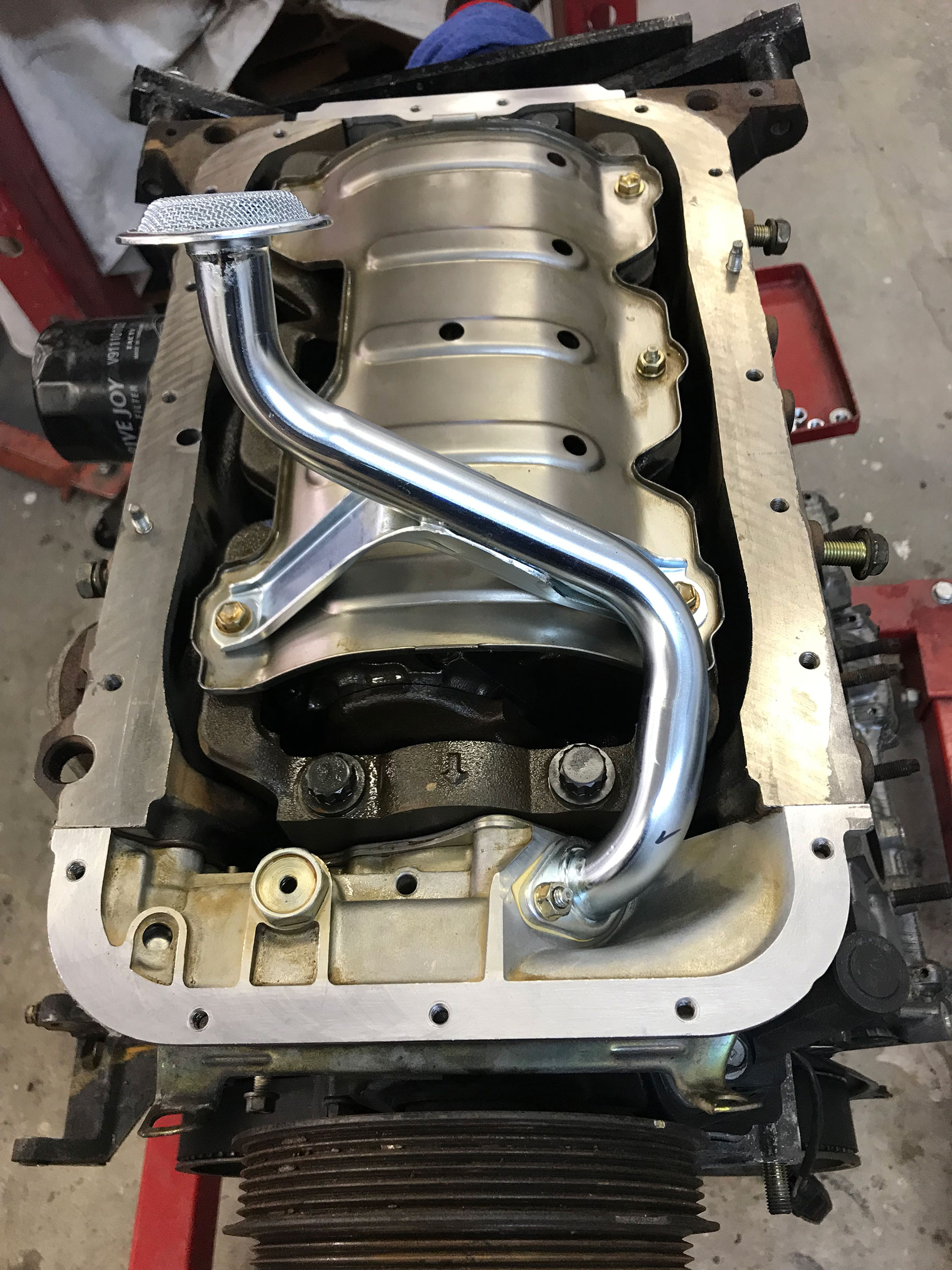
- Install the new oil sump gasket and oil sump onto the block. Re-arrange the fasteners on the 5VZ oil baffle to accommodate the new oil sump (if necessary). Note: do NOT use the 3VZ baffle that fits between the block and pan. Tighten the 6mm nuts to 66 lbs-in. Tighten all nuts and bolts on the oil baffle, and re-check the torque on the 6mm sump nuts. See pic 6a
-
- Pic 6a – Oil pan sump installed
-
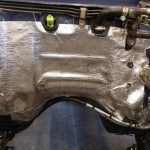
- Apply a bead of the Toyota FIPG (sealer) to the new oil pan. Be sure to drive the sealer into the grooves of the oil pan and around the mounting holes to ensure a good seal.
- Install the oil pan on the engine block and torque the mounting bolts to 52 lbs-in. using a “criss-cross” pattern. Make a second pass to re-check fastener torque. Install and tighten the provided oil drain plug and gasket in the oil pan. See pic 6b
-

- Pic 6b – Oil pan installed (4×4 IFS pan)
-
- Turn the engine back over in the stand.

Engine Preparation
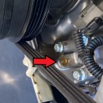
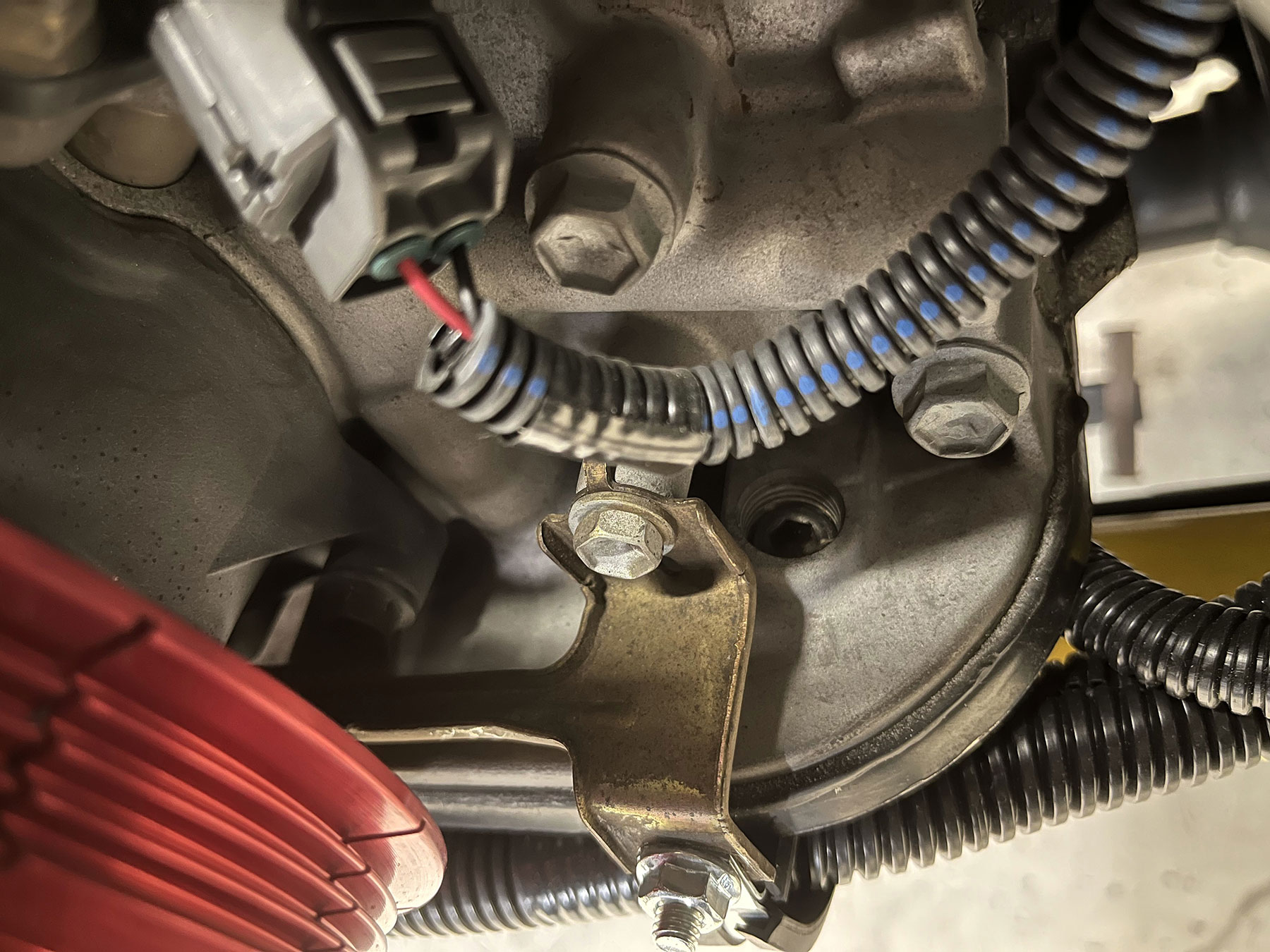
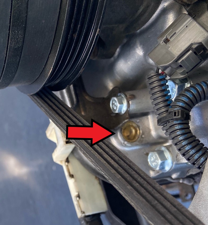
- Install the engine mount and brackets that will be used on the engine block. If the recipient is an ’88-‘95 3.0L 3VZ Pickup/4Runner, this engine will bolt in place using ’91-’95 4Runner/4×4 Pickup engine block brackets/mounts; no modification to engine mounts will be needed. If using the original 3VZ transmission, this can also be used in its original position. If using ’91-’95 3VZ mount brackets, the A/C bracket may need to be carefully ground flush on one bolt-boss until the AC bracket will properly fit the engine block. See pic #7. Some 5VZ applications will have a small drain pipe below the coolant drain plug. This drain pipe may interfere with the engine mount. In this case, simply drive the small drain pipe from the engine block; it serves no purpose but to direct coolant flow while draining. See pics #8 & 8a
-
- Pic 7 – 5VZ A/C bracket modified for 3VZ engine mount brackets
-
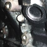
- Pic 8 – Coolant drain plug removed
-
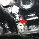
- Pic 8a – Coolant drain plug in place
-
- If using an ORS full-replacement High Pressure Fuel Hose, install banjo fitting on fuel rail. See Fuel Hose Instructions. Also, this is a good time to install one end of the fuel return hose to the fuel pressure regulator.
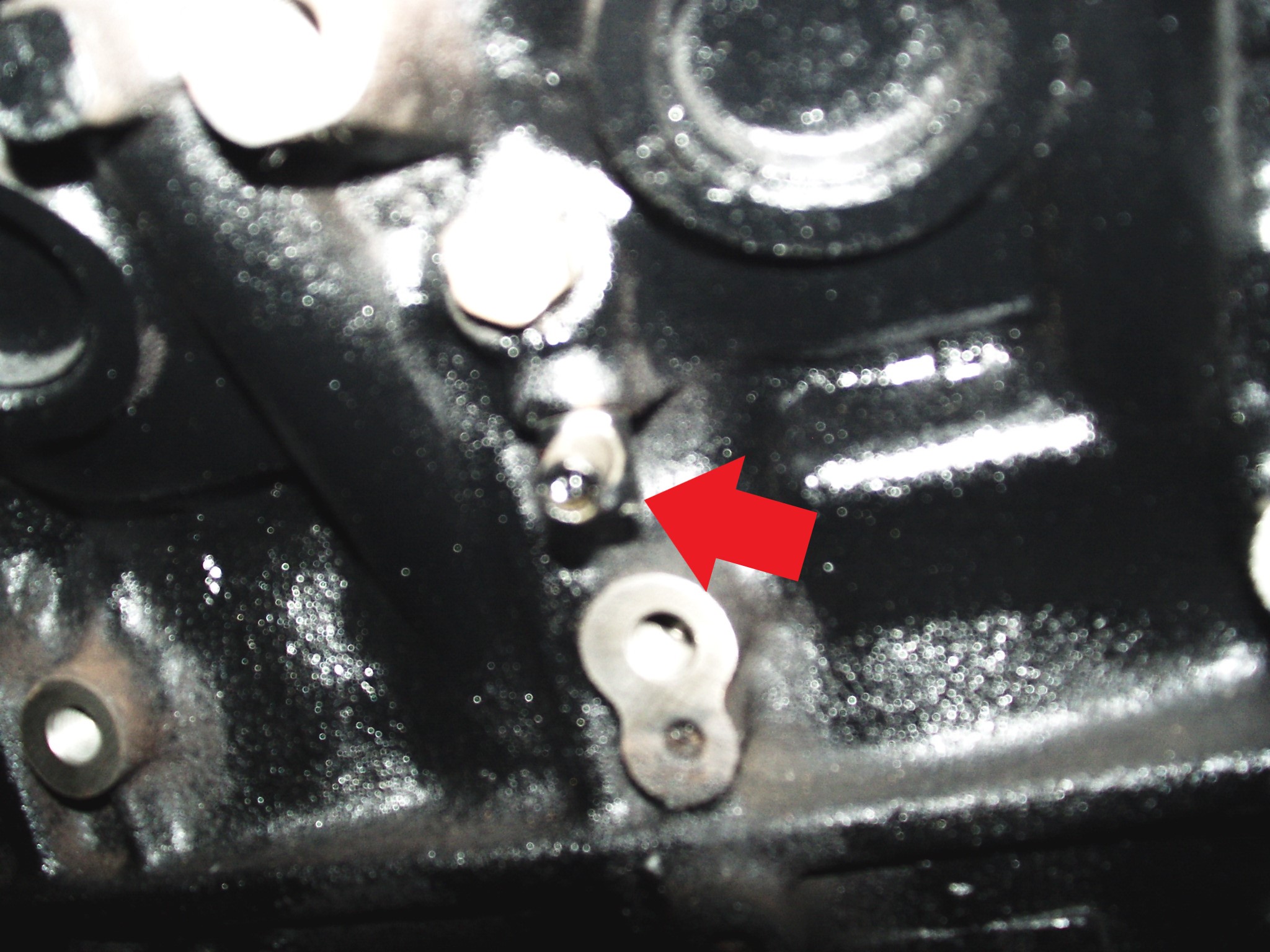
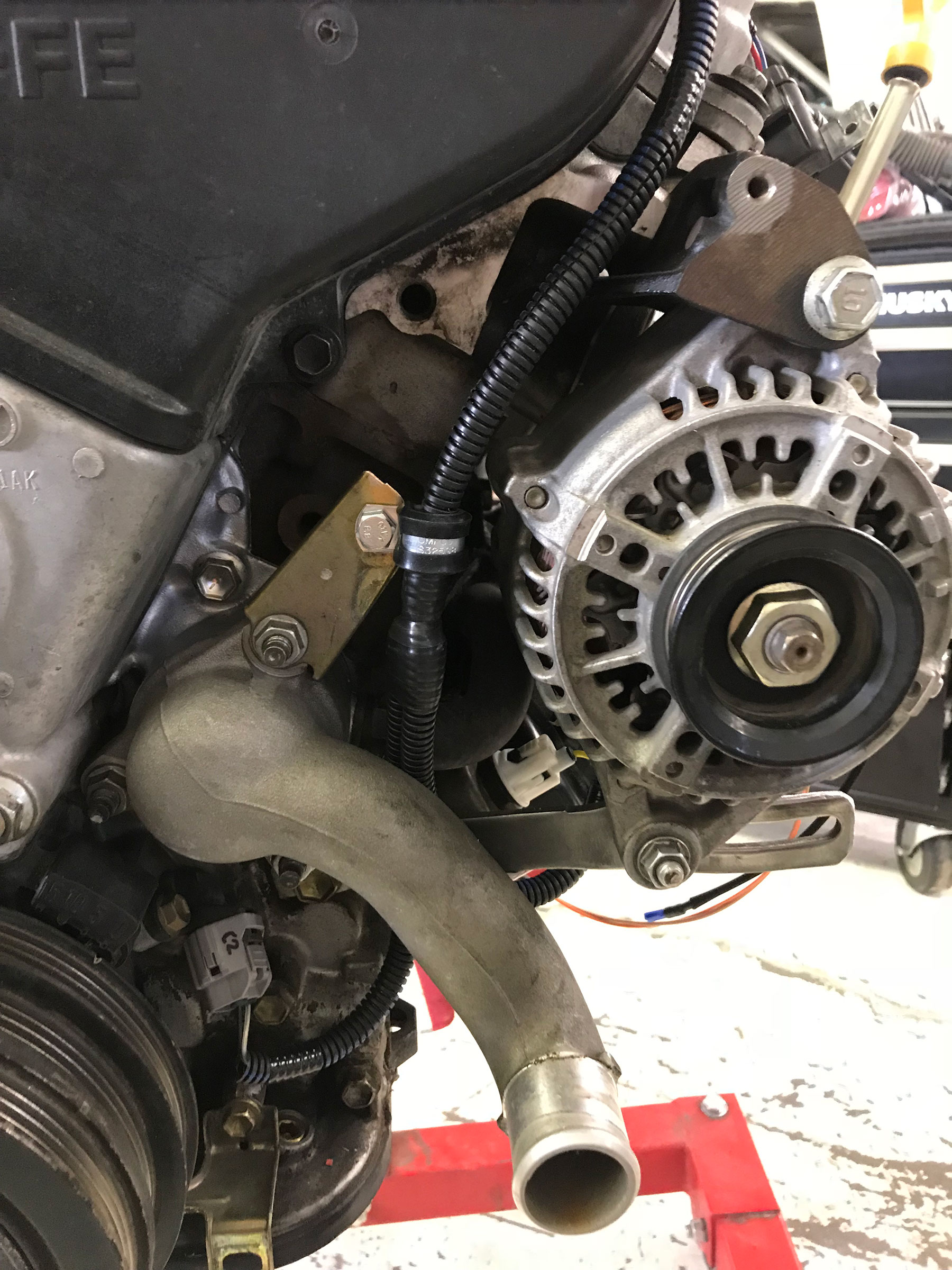
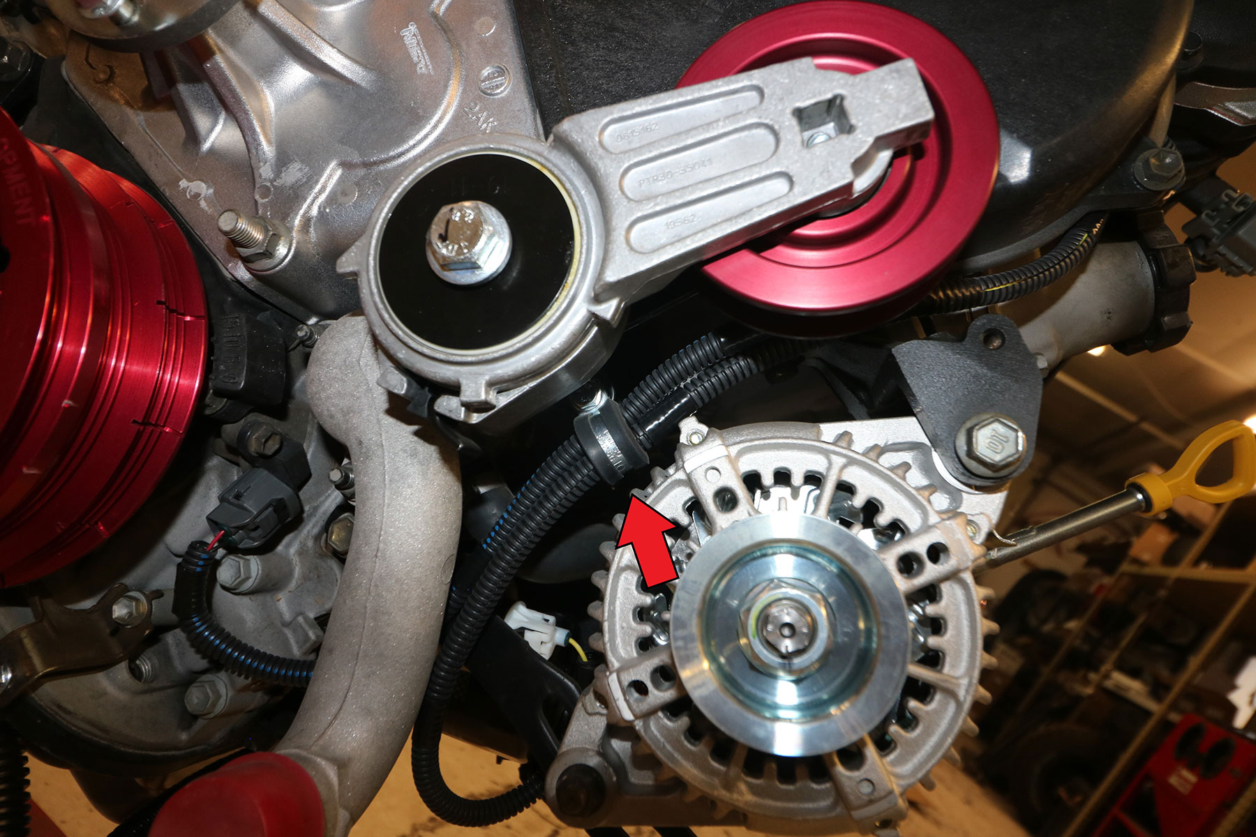
- If applicable: The lower alternator bracket often interferes with the steering shaft. To eliminate this problem, the adjuster bolt can be removed and the adjuster-bolt retainer can be cut from the end of the bracket. The alternator belt can then be adjusted with a pry-bar like the 3VZ or 22R alternator. See Pics #9 & 9a
-
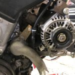
- Pic 9 – Lower alternator bracket after modification
-
- Pic 9a – Lower alternator bracket before modification
-
- 4×2 Cab/Chassis recipients (inc. RV): Install the ORS lower alternator bracket. This will be necessary for alternator clearance. This will require alternator belt PN k040405.
- In some cases, the alternator body may interfere with the steering shaft. In this case, a shorter alternator drive-belt may be needed. Drive-belts can be purchased at most parts stores based on width, type and size.
- Install accessories on the 5VZ engine (Power Steering pump, Alternator, A/C compressor). If using the A/C compressor from the original application, see here.
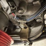
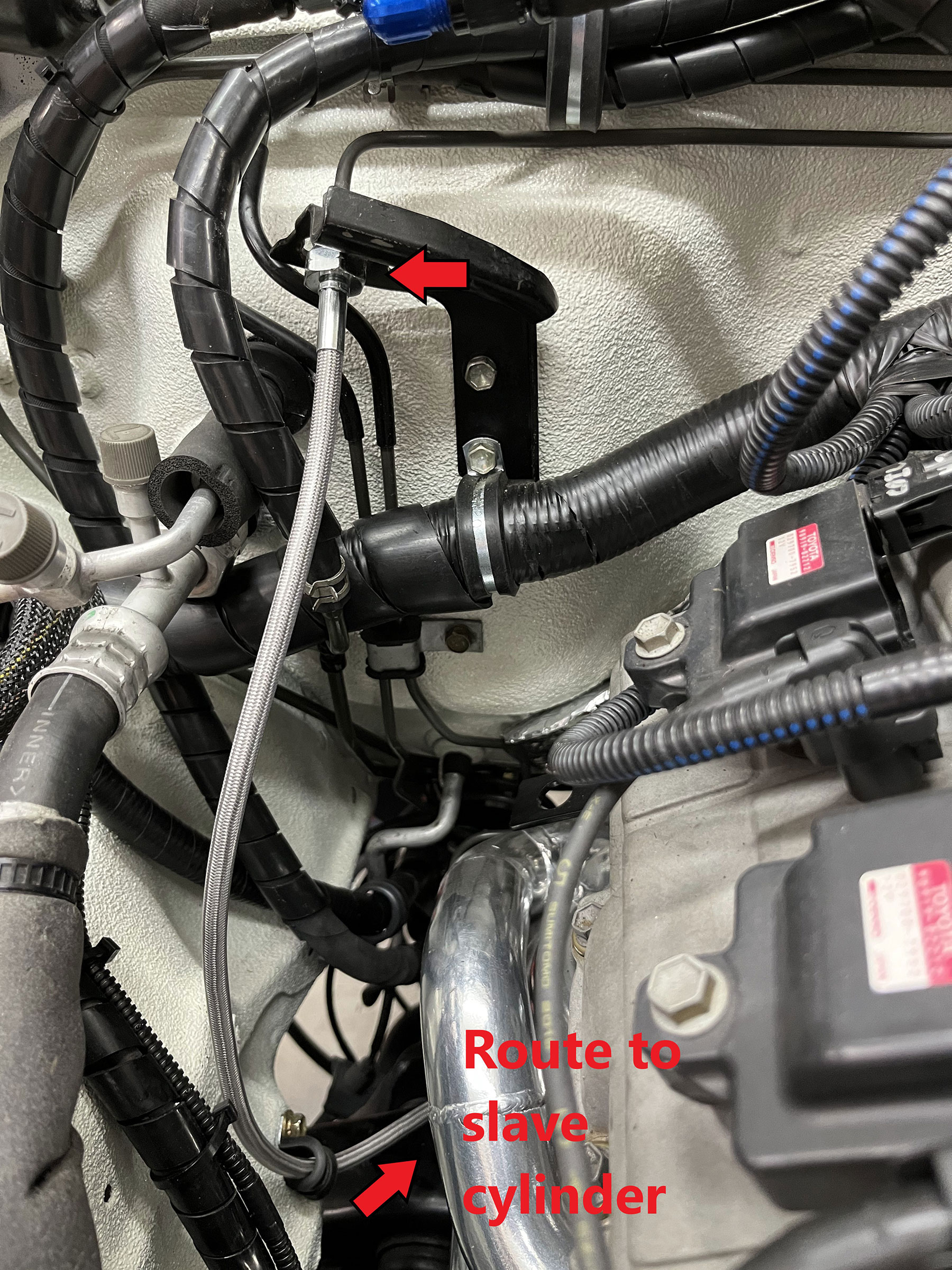
- Manual-Transmission w/ RH Slave Cylinder: Install the clutch hose bracket on the RH cylinder head. The proper mounting hole is located in the rear upper corner of the RH cylinder head, 2nd from the rear. If using the ORS Header Set, or simply as a different alternative, we recommend the use of our clutch hose, specifically used with the header set; this will bypass the header pipe. See pic #10
-
- Pic 10 – Clutch hose for RH-slave cylinder
-
Exhaust
All 5VZ donor vehicles utilized a RH-exhaust system. Most donor vehicles came with a LH-exhaust system. To clear the slave cylinder, front driveshaft, fuel tank and fuel/brake plumbing, it is recommended to swap to a LH-exhaust system, using either ORS exhaust product. The ORS Exhaust Crossover Pipe with donor exhaust manifolds; OR the ORS 5VZ Performance Header set to replace donor manifolds and increase power output.
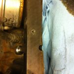
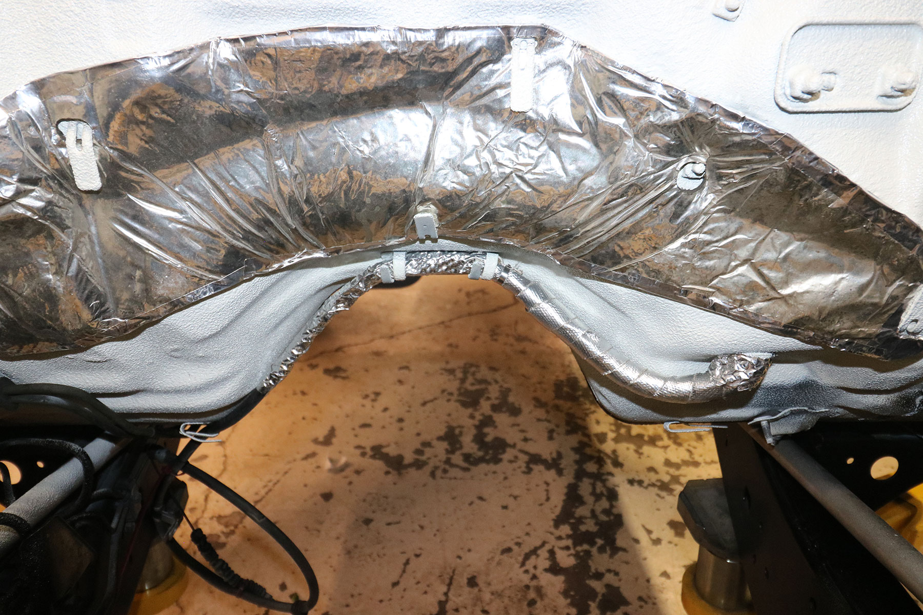
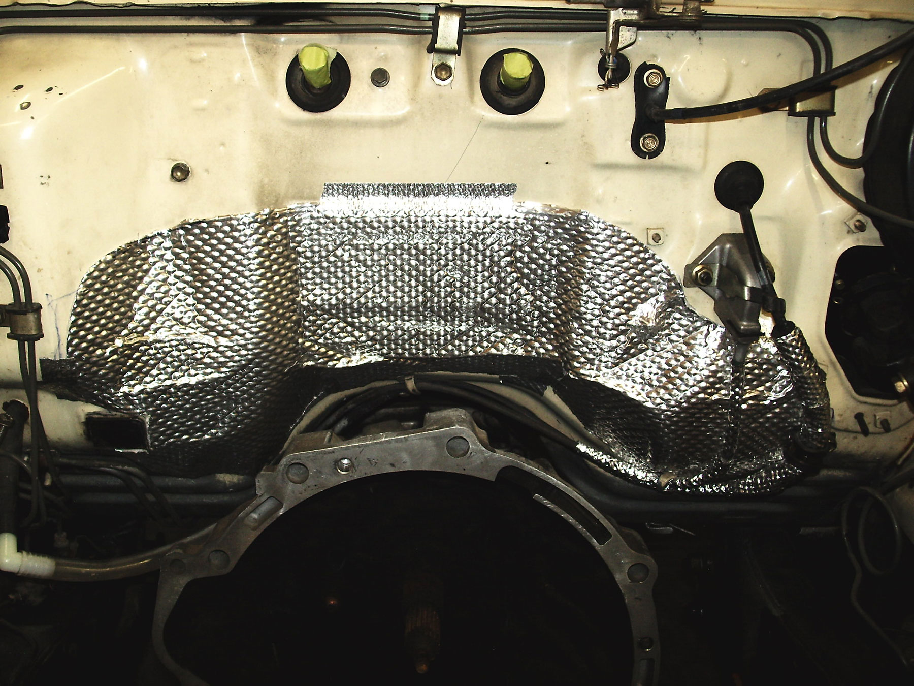
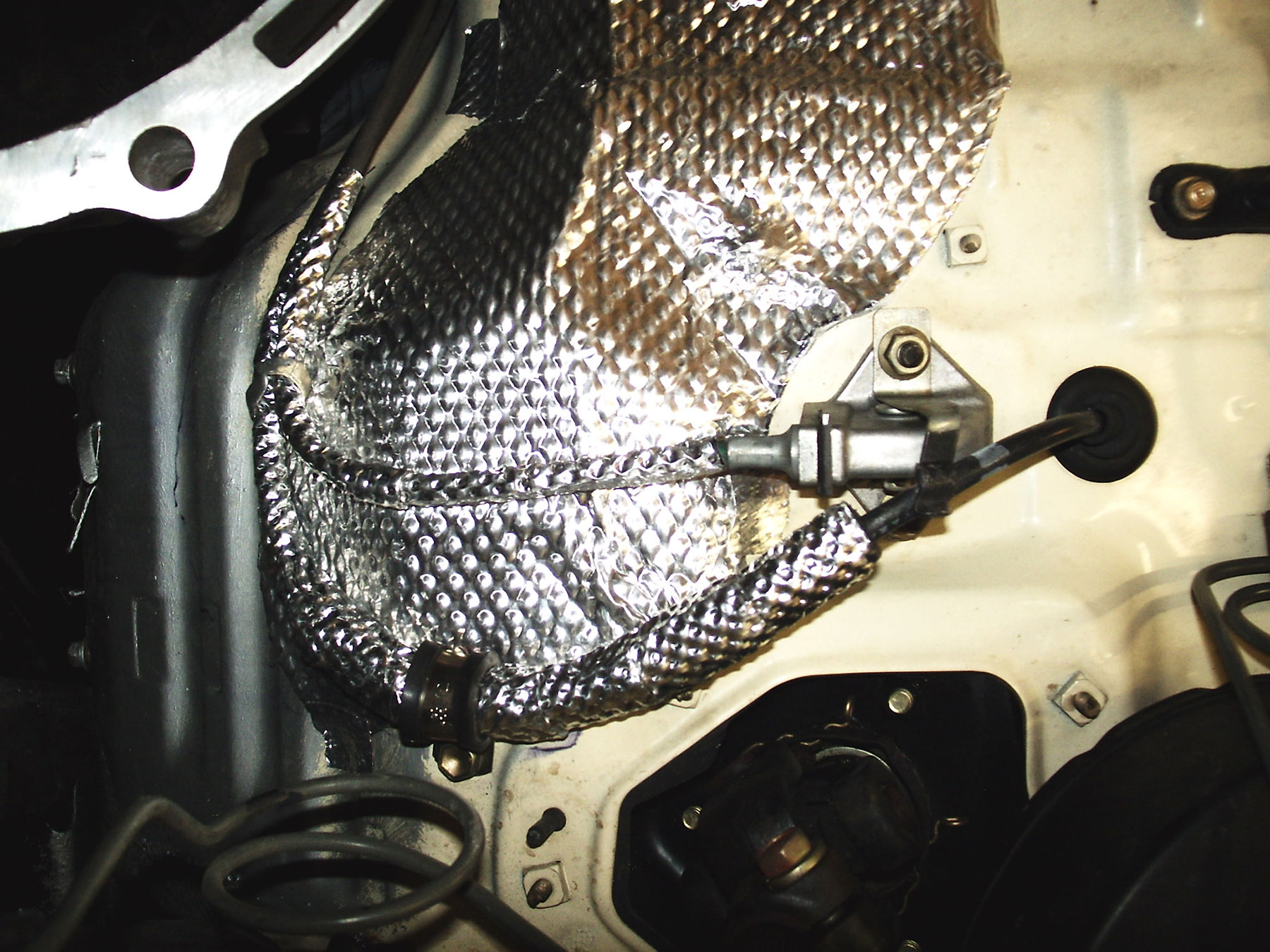
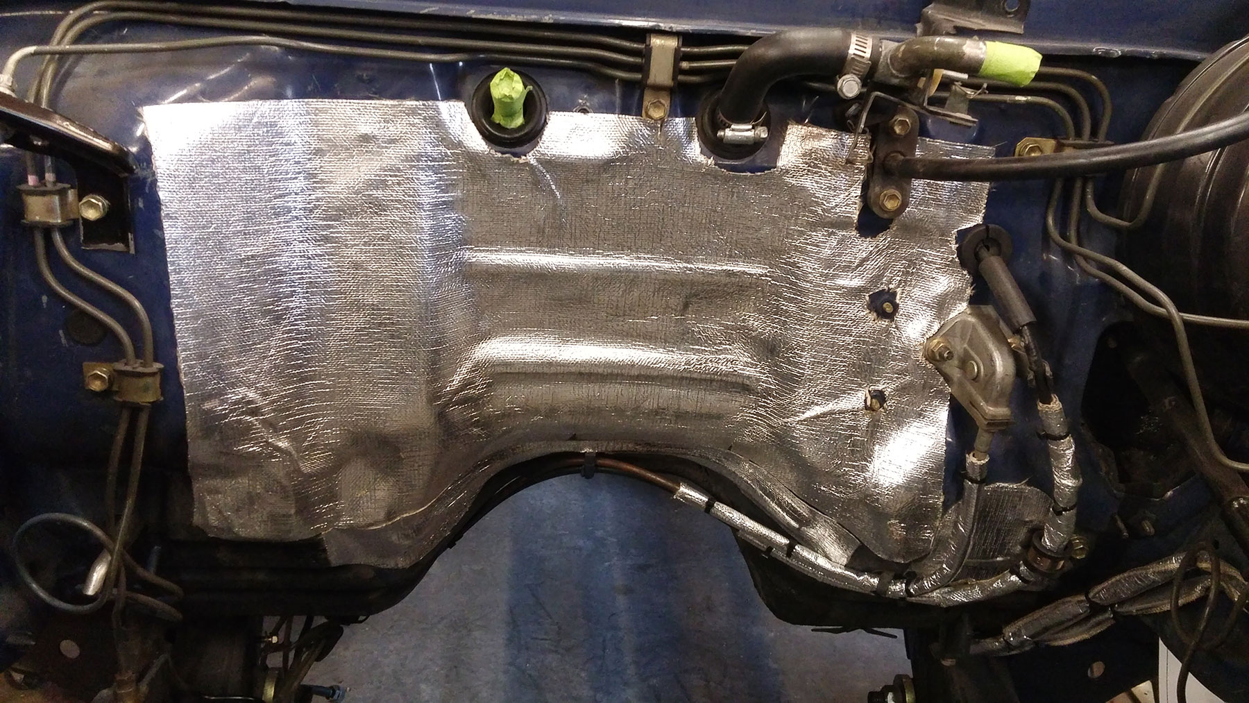
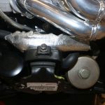
When any kind of Crossover-pipe (Y-pipe) is in use, the use of heat shielding on the firewall, speedometer cable, and parking brake cable is required to prevent excessive heat under the hood, on the firewall, and against the cables. This can be done with the OEM heat-shield, or custom (adhesive) heat shield cut and applied to the firewall. See pics 10a-10d
Off Road Solutions Exhaust Crossover Pipe (using OEM manifolds) (ORS-EC070xxxx)
The ORS Crossover Pipe includes the following:
- 1 x Exhaust crossover pipe
- 1 x 3-bolt 2.5” weld-on flange
- 1 x 3-bolt 2.5” exhaust gasket
- 6 x exhaust studs
- 9 x exhaust nuts
- 3 x 10mm bolts
- 3 x 10mm flat washer
- 2 x exhaust donut style gaskets
- There is NO warranty on the ORS 3.4L Exhaust Crossover Pipe.
- The ORS Crossover Pipe is built from mild steel. Ceramic coating is an option when purchasing this pipe, to prevent rust and aid in heat reduction. If a “non-coated” version was purchased we recommend either ceramic coating or the use of high-quality exhaust paint. If using exhaust paint, we also recommend the use of an internal spray coating, such as ‘internal header coating’. These coatings are designed to trap the heat in the pipe, reducing under-hood temperatures. ORS does NOT recommend wrapping the ORS Crossover Pipe with exhaust wrap; this will diminish the life of the Crossover Pipe.
- Before coating, be sure to thoroughly clean the crossover pipe inside and out, as oil will be present from manufacturing. This is necessary to remove oil deposits which prevent the paint from adhering to the pipe. Read and follow the paint manufacturer’s instructions.
- We also highly recommend the use of heat shielding on the firewall, speedometer cable, and parking brake cable to prevent excessive heat under the hood, on the firewall, and against the cables. See pics 10a-10d.
-
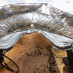
- Pic 10a – OEM Firewall heat shield installed
-
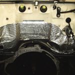
- Pic 10b – Aftermarket Heat-Shield material applied to firewall and cables
-
- Pic 10c – Aftermarket Heat-Shield material applied to firewall and cables
-
- Pic 10d – Aftermarket Heat-Shield material applied to firewall and cables
-
- Pic 10e – Firewall heat shield fitted to Collector flange
-
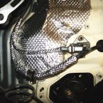
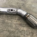
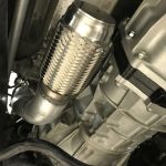
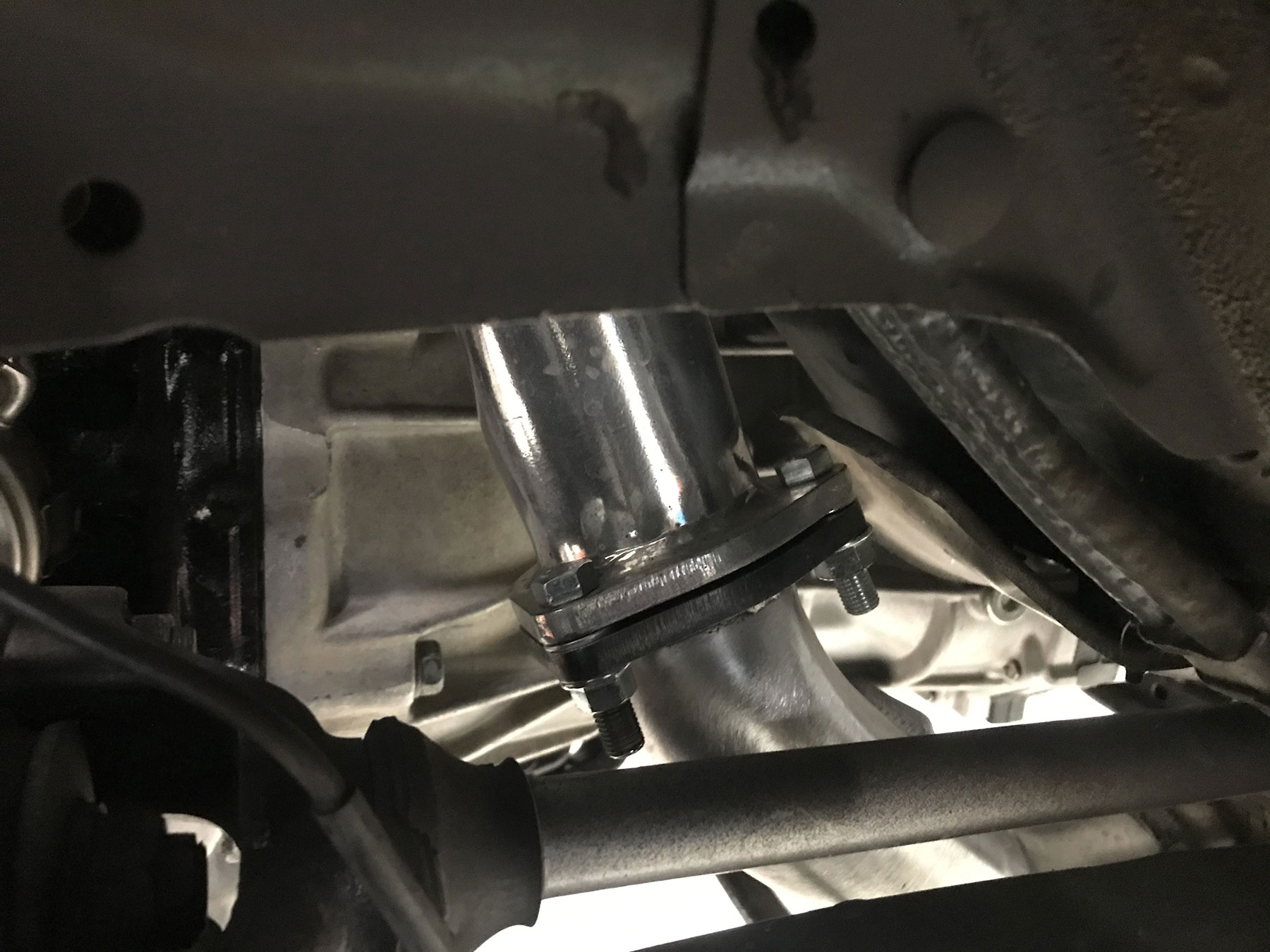
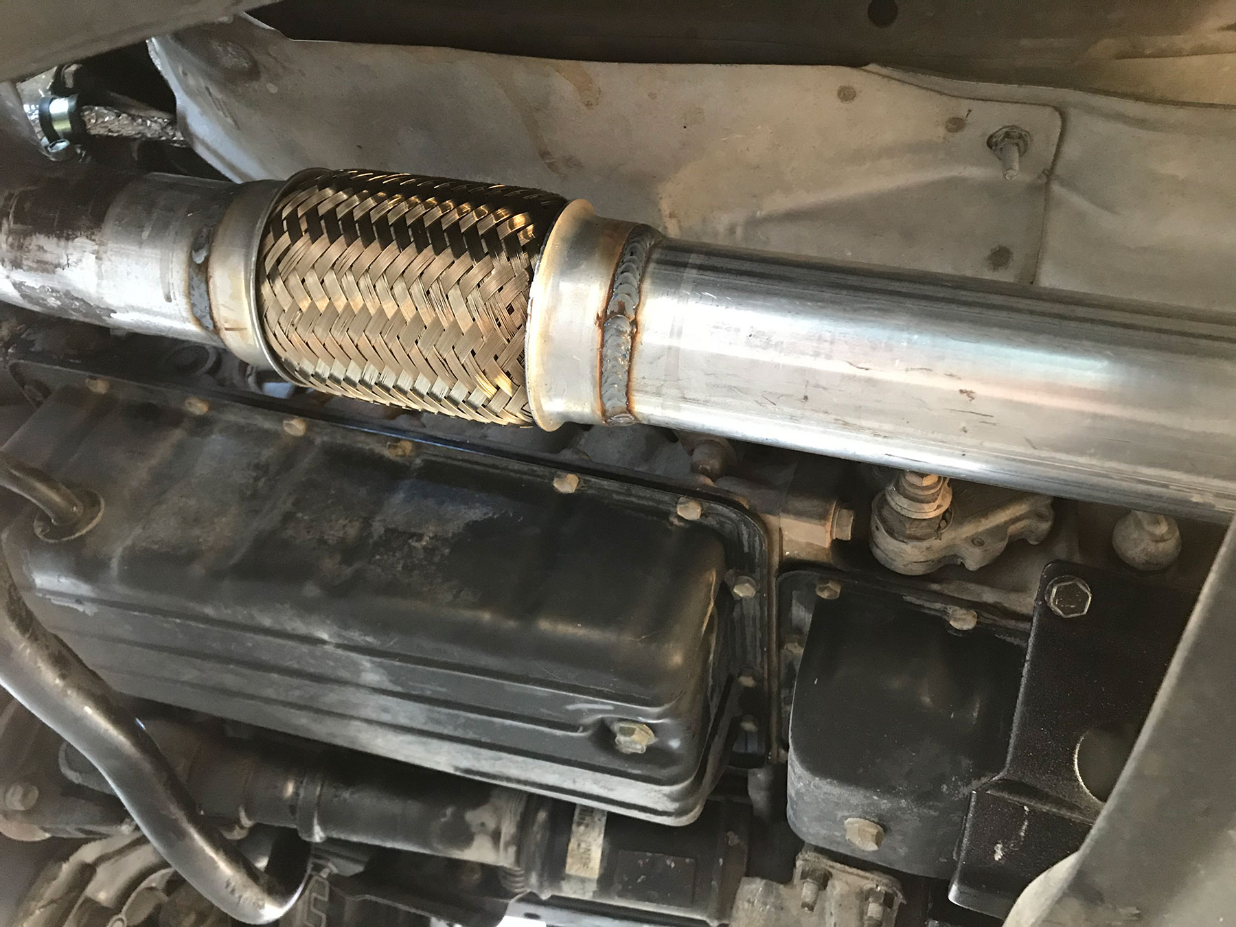
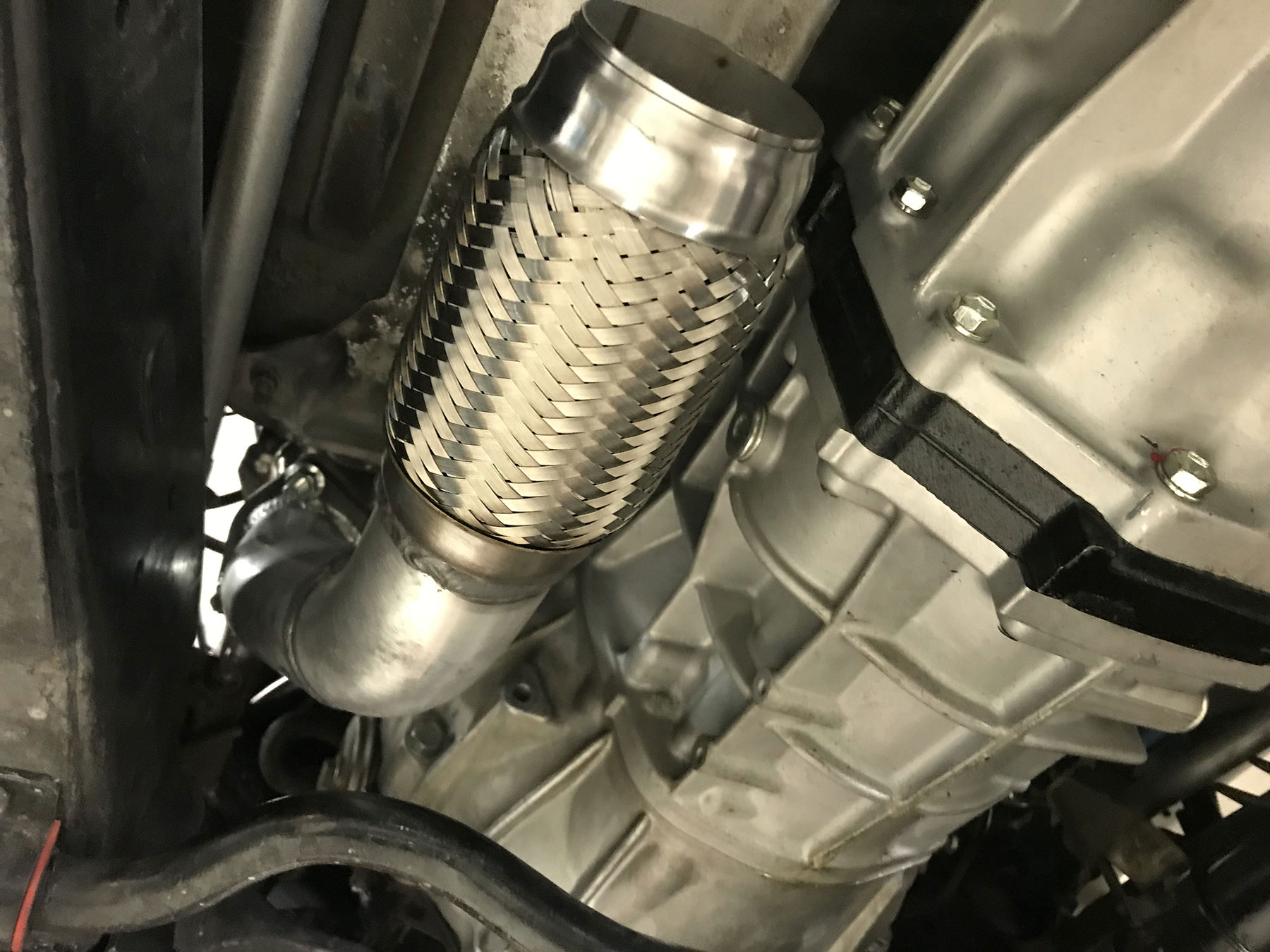
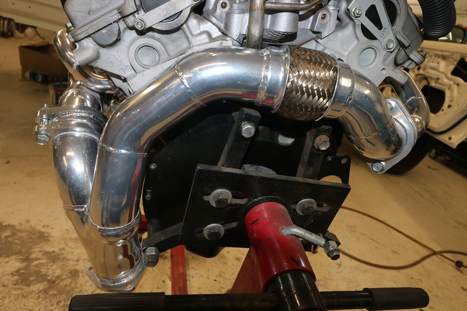
- ORS HIGHLY recommends the use of a flex coupler in the exhaust system near the outlet of this crossover pipe. The weight and strain of the entire exhaust system can and will cause this crossover pipe or exhaust manifolds to fail prematurely. Once again, this pipe is not covered under any warranty. ORS can provide a flex coupler if needed. See picture #11
-
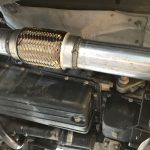
- Pic 11 – Flex coupler installed down-stream of Crossover Pipe/Header
-
- We recommend installing this pipe while the engine is out of vehicle. In most cases, the transmission must be removed in order to install the ORS Crossover pipe with the engine in the vehicle.
- The additional weld-on flange is a starting point for the rest of the exhaust. Install the 10mm bolts through the flanges with the flat washers on the bolt head side.
- We recommend installing the new exhaust studs in the rear of the exhaust manifolds.
- The provided donut style exhaust gaskets are placed between the crossover and the exhaust manifolds.
- Modify or remove the heat shield on the inside LH frame-rail (over torsion bar) to clear the collector flange on the ORS crossover pipe. We have found that heat no longer builds up in this area of the pipe and this heat shield is not needed.
- Bend the upper end of the heat shield on the firewall to clear the collector flange. We normally remove this shield during engine install, then fit and re-install after the pipe and engine are in place. See pic 10e.
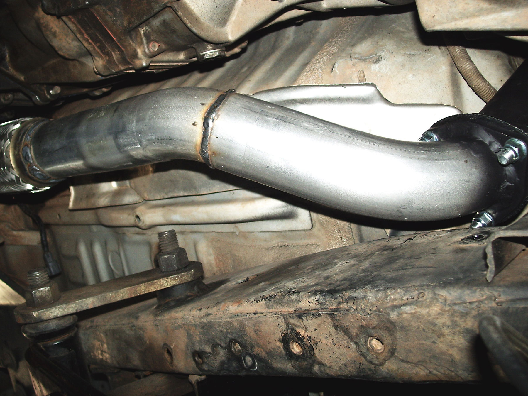
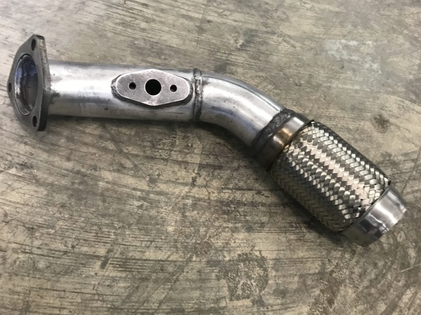
- The outlet of the ORS Crossover Pipe will be aimed toward the top of the frame. To achieve necessary clearance, this may require that 2 exhaust bends are used immediately after the collector, the first pointing toward the transmission and the second pointing to the rear of the vehicle. It may be necessary to cut and join these bends together due to space constraints. ORS also offers a down-pipe for the for certain Crossover Pipes, which will get the exhaust around the frame and pointed to the rear of the vehicle. See pictures #12, 13, & 13a.
-
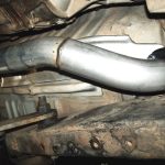
- Pic 12 – Down-pipe fabricated to clear frame
-
- Pic 13 – ORS Down-Pipe for Crossover Pipe
-
- Pic 13a – ORS Down-Pipe for Crossover Pipe
-
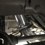
- When using a donor 5VZ-based manual transmission (LH slave-cylinder), the version of the ORS Crossover Pipe “with lower flange loose” will be required. These applications may require an extension of the collector or careful flange placement before the collector flange is installed. This will ensure the necessary clearance to the clutch slave cylinder on the 5VZ bell-housing. It may be necessary to shield the rubber clutch-fork boot from the exhaust heat. See pic #14 & 15
-
- Pic 14 – Crossover pipe extended around clutch LH slave cylinder
-
- Pic 15 – Crossover pipe extended, for LH slave, in vehicle for mock-up
-
- When used on column-shift A/T models, (such as 4×2 Cab/Chassis, RV), modification of the shift linkage system will be necessary for clearance to the crossover pipe. Here are some recommended setups:
- ORS offers a modification service to the original 3VZ shift linkage for exhaust clearance, call for details.
- This may be done by converting to a floor shifter.
- 5VZ-FE 2WD Tacoma models with the column shift option had a simple bell-housing-mounted bracket that retained the shifter cable end near the transmission.
- 5VZ-FE T100 models had a frame mounted shift linkage that was mounted rearward of the transmission shift lever.
ORS 3.4L 5VZ-FE Performance Header Set (ORS-EC077)
This kit includes the following:
- 1x LH Header Pipe
- 1x RH Header Pipe
- 1x Crossover Pipe (Y-pipe)
- 12x 10mmx1.25 x 25mm bolt
- 4x 10mmx1.25 x 55mm bolt
- 1x Exhaust flange, 3 bolt, 2.625″
- 1x Gasket, 3 bolt, 2.625″ flange
- 3x Flat Washer, 10mm
- 7x Lock Nut
- 3x Bolt, 10mm x 40mm x 1.25
- 1x Exhaust Manifold Gasket Set, 5VZ-FE
- 1x Heat Sleeve, Hook and Loop – 9″ cut
- This header set will NOT fit a vehicle using the 5VZ donor R150 transmission (w/ LH slave cylinder).
- If using the A340H auto-transmission, modification to the trans-pan dipstick tube may be necessary to clear the lower end of the Crossover-Pipe.
- A/T models w/ a column shifter may require shifter changes to clear the Crossover Pipe.
- ORS does NOT recommend wrapping the ORS Header Set with exhaust wrap; this will diminish the life of the Header Set.
- There is no official warranty on the ORS 3.4L 5VZ Performance Header Set, please contact ORS with any initial concerns before installation. This header set is designed for ’79-’95 Toyota Trucks and 4Runners receiving a 3.4L 5VZ engine conversion, utilizing a LH-exhaust system. This header set will work with all A/T configurations along with R151 and 3VZ R150 M/T transmission applications. This header set will not work with the 5VZ 3.4L R150 manual transmission, due to the LH-slave cylinder setup.
- This is not a step-by-step guide; these steps only list the key points of the install.
- We highly recommend the use of heat shielding on the firewall, speedometer cable, and parking brake cable to prevent excessive heat under the hood, on the firewall, and against the cables. See pics 10a-10d.
-
- Pic 10a – OEM Firewall heat shield installed
-
- Pic 10b – Aftermarket Heat-Shield material applied to firewall and cables
-
- Pic 10c – Aftermarket Heat-Shield material applied to firewall and cables
-
- Pic 10d – Aftermarket Heat-Shield material applied to firewall and cables
-
- Pic 10e – Firewall heat shield fitted to Collector flange
-
- ORS HIGHLY recommends the use of a flex coupler in the exhaust system near the outlet of the crossover pipe. As with any exhaust, the weight and strain of the entire exhaust system can and will cause the crossover pipe/headers to fail prematurely. Once again, this header set is not covered under any warranty. ORS can provide a flex coupler if needed.
-
- Pic 11 – Flex coupler installed down-stream of Crossover Pipe/Header
-
- Although it is easier to install this header set with the engine out of the vehicle, it can also be installed with both the engine and the transmission in place.
- You may need to bend the upper end of the heat shield on the firewall to clear the collector flange. We normally remove this shield during engine install, then fit and re-install after the crossover pipe and engine are in place. See pic 10e.
- When used on column-shift A/T models, modification of the shift linkage system will be necessary for clearance to the crossover pipe. Here are some recommended setups:
- ORS offers a modification service to the original 3VZ shift linkage for exhaust clearance, call for details.
- This may be done by converting to a floor shifter.
- 5VZ-FE 2WD Tacoma models with the column shift option had a simple bell-housing-mounted bracket that retained the shifter cable end near the transmission.
- 5VZ-FE T100 models had a frame mounted shift linkage that was mounted rearward of the transmission shift lever.
- This may be done by converting to a floor shifter.
- 5VZ-FE 2WD Tacoma models with the column shift option had a simple bellhousing-mounted bracket that retained the shifter cable end near the transmission.
- 5VZ-FE T100 models had a frame mounted shift linkage that was mounted rearward of the transmission shift lever.
- The OEM exhaust manifolds and exhaust studs will be removed and discarded.
- The exhaust manifold surfaces on the engine head must be thoroughly cleaned before installation. In the process of cleaning, take care not to wear down or damage the aluminum head surface.
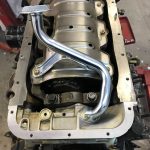
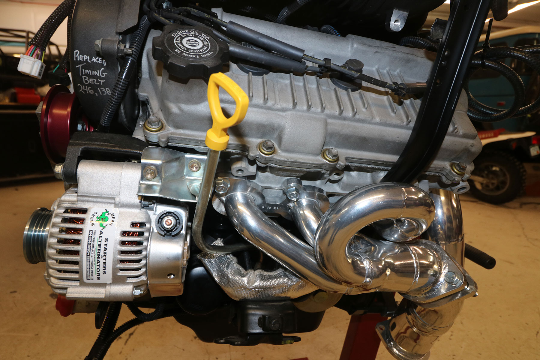
- Using the provided exhaust manifold gaskets, 10mm x 25mm bolts and 10mm flat washers, install the LH and RH header pipes to the engine head. Tighten the LH and RH header pipes to 30 ft-lb, starting from the center and working outward in an even pattern. Make one or two more passes, checking torque, to be sure the sealing surface is evenly seated.
- Install the crossover pipe (Y-pipe) to the back of the header pipes using the 10mm x 50 bolts and 4 lock nuts. Leave crossover pipe loose. Check clearance on the crossover pipe to the engine heads and tighten the crossover pipe x header pipe bolts once this position/clearance is ideal. These bolts/nuts do not need excessive torque. See pics #16,17,18
-
- Pic 16 – Header Set install, LH side
-
- Pic 17 – Header set installed, RH side
-
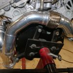
- Pic 18 – Header set installed, from rear
-
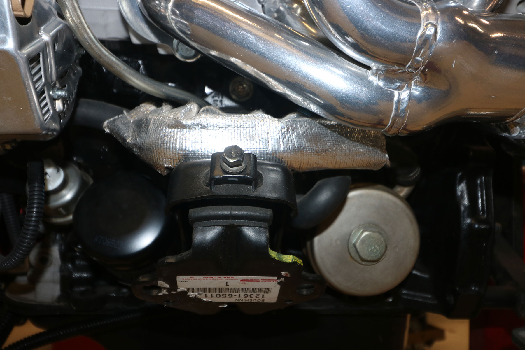
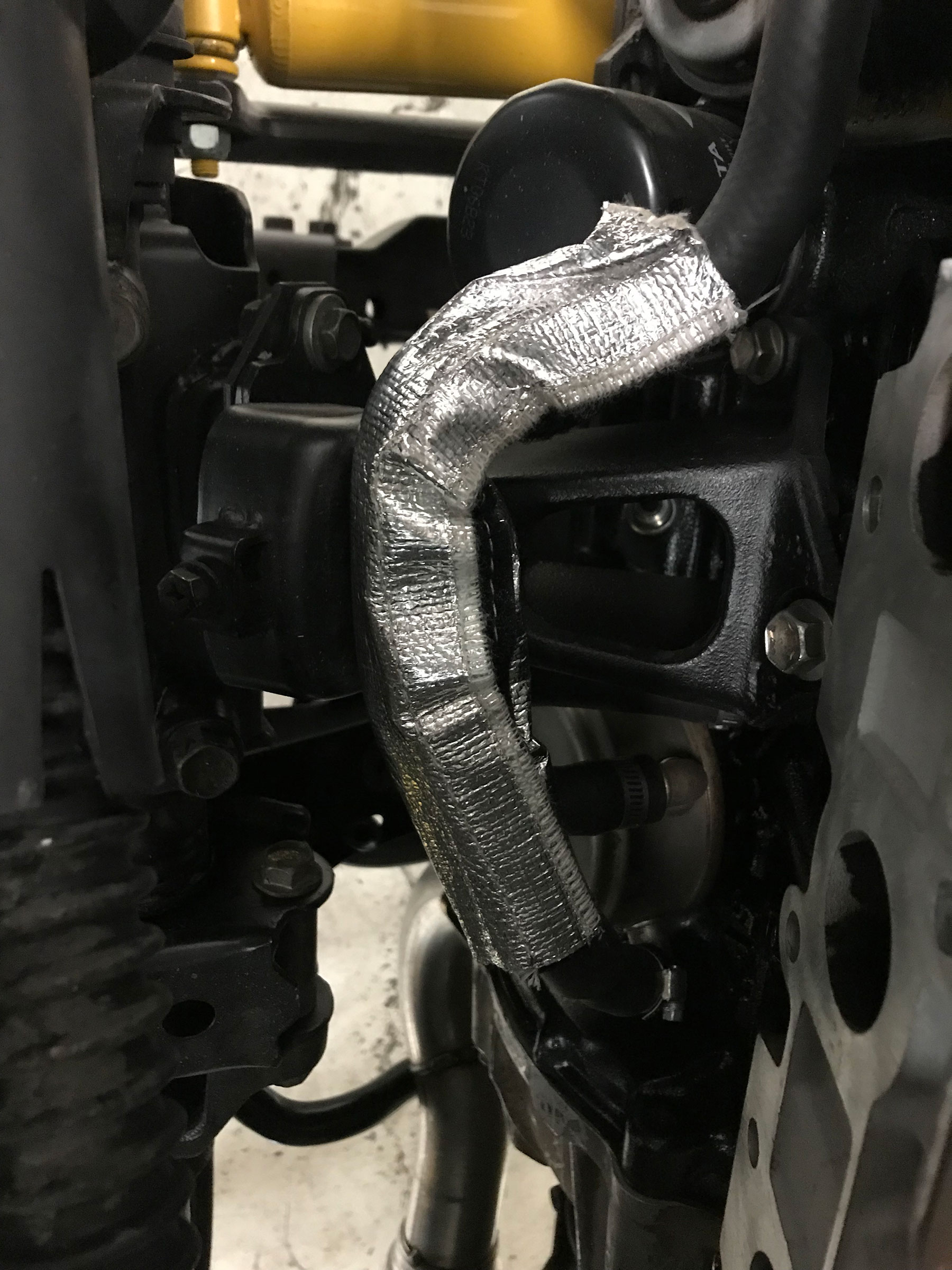
- The provided length of heat shield sleeve is to be installed over the oil cooler coolant hose directly under the LH header pipe for longevity of that hose. Simply wrap the heat shield sleeve around the oil cooler hose and securely close the sleeve. Pic #19 & 19a
-
- Pic 19 – Heat wrap on oil cooler hose
-
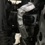
- Pic 19a – Heat wrap on oil cooler hose
-
Transmission Prep, When Using Donor Transmission
If installing a gear-driven transfer case to the rear of an A340F or R150F donor transmission, an adapter must be used:
Gear-drive x A340F Adapter Install (MAR-MCTC-133)
Note: the following section closely matches the install of this Adapter for use behind an R150 manual-transmission from a 5VZ donor vehicle.
The Gear Driven Transfer Case needed for this conversion is found in a ’79-’95 Toyota 4-cylinder 4×4 Manual-Transmission Pickup/4Runner. If not already, this transfer case must be fitted with a 23-spline input shaft and a ‘top-shift’ shifter configuration.
- Remove the original transfer case from the rear of the 3.4L A340 automatic transmission (8 bolts).
- Steps 2-5 may only be necessary on some A/T models: Remove the extension housing from the rear of the transmission.
- Using a gear puller or necessary tool, remove the output collar (sleeve) from the transmission output shaft.
- Remove the output seal and output bearing from the extension housing.
- Thoroughly clean the extension housing and sealing surfaces to the transmission.
- Apply a small layer of Loctite to the mating surface of the new seal housing. Using a press or a hammer, carefully press the new seal housing into the transmission extension housing. The seal housing should be installed so that the seal end is facing the transfer case. The seal in the seal housing will seal on the transfer case input shaft. Apply a thin coat of grease to the inside of the seal.
- Locate the new 23-spline coupler provided with the adapter kit. Place the coupler on the end of the transmission output shaft. Turn the coupler until the splines on the inside of the coupler have lined up with the splines on the output shaft.
- Using a large dead blow (non-metalic) hammer, drive the coupler over the transmission output shaft until it cannot be driven any further.
- Some A/T models only: Apply a thin coat of the provided silicone sealer to the rear of the transmission. Install the extension housing to the rear of the transmission using the original hardware. Torque the mounting bolts to 27 ft-lb.
- Locate the new aluminum transfer case adapter plate. Thoroughly clean the mating surfaces of the adapter and the mating surface (front) of the gear driven transfer case. Apply a paper gasket or silicone sealant to the mating surface. Using the provided and appropriate hardware, bolt the adapter to the front of the gear-driven transfer case. Torque the mounting bolts to 30 ft-lb.
- Thoroughly clean the rear mating surface of the extension housing and the front mating surface of the aluminum adapter. Apply a thin coat of the provided silicone sealant to the mating surface of the extension housing. Align the transfer case input shaft with the output coupler (be careful not to damage output seal) and slide the transfer case onto the rear of the transmission. Use the appropriate bolts in the proper location. Torque all mounting bolts to 27 ft-lb.
5VZ Automatic Transmission Oil Pan
Note: This section only pertains to the use of a donor A340F transmission from a 5VZ application when used in a ’79-‘95 Pickup/4Runner 4×4 application. This section does not pertain to 4×2 vehicles and those using the original A340H transmission (from 3VZ application). The purpose of this modification is to gain the necessary clearance between the front driveshaft and the oil pan dipstick on the donor transmission. This will move the dipstick tube to the LH side for more clearance.
This is best done while the transmission is separated from the engine.
Many of these are no longer available as a new part. The ideal application for these parts is a 5VZ T100 4×4. The corresponding 4×2 T100 parts can also be used, with modification. These are the required parts to convert the transmission oil pan:
- Transmission oil pan
- Dip stick tube
- Dip stick
- Sealant, recc. Toyota orange FIPG
- New bulk hose for trans cooler hoses (3/8” transmission oil cooler hose)
- #6 hose clamps, x4
- Securely support the transmission so that the pan can be accessed. Be sure the transmission fluid is fully drained.
- Remove the 6mm bolts that retain the pan to the transmission. Remove the transmission pan, being careful not to damage the sealing surface.
- Thoroughly clean the transmission’s sealing surface.
- Be sure that the new pan and valve body are very clean. Articles as small as lint from a rag can cause damage to the transmission valve body.
- Apply a thin coat of Toyota orange FIPG (or equivalent sealer) to the new pan’s sealing surface. Be sure to work the sealer into the grooves of the pan and around the mounting holes.
- Install the new pan on the transmission. Torque the mounting bolts to 65 in-lb. in a “criss-cross” pattern.
- The dipstick tube can be installed once the engine is mounted to the transmission.
- The oil cooler hoses should be installed between the original transmission oil cooler hard lines and the transmission cooler, normally in the lower portion of the radiator. If there will be heavy use of the trans, such as towing or difficult off-road use, an auxiliary transmission cooler can also be added in-line , in the path of these cooler hoses.
Note: If engine wiring is not already installed on the engine, this is normally a convenient time to do so. The engine wiring can be installed with the engine in place, but it easier while the engine is out. If using the ORS Engine Wiring Conversion Harness, refer to wiring install instructions. See pics 49-55
-
- Pic 49 – Engine Wiring Install – Be sure to clamp wiring where indicated

-
- Pic 50 – Engine Wiring Install – Be sure to clamp wiring where indicated
-
- Pic 51 – Engine Wiring Install – Be sure to clamp wiring where indicated

-
- Pic 52 – Engine Wiring Install – Be sure to clamp wiring where indicated
-
- Pic 53 – Engine Wiring Install – Be sure to clamp wiring where indicated
-
- Pic 53a – Engine Wiring Install – Be sure to clamp wiring where indicated
-
- Pic 54 – Engine Wiring Install – Be sure to clamp wiring where indicated
-
- Pic 55 – Engine Wiring Install – Be sure to clamp wiring where indicated
Frame Mounts
Notes regarding engine mounts:
- If recipient was originally a 3VZ vehicle, no changes will be necessary to the frame mount brackets. Be sure frame brackets are clean and free of rust.
- If recipient was originally a 22R (or 22-RE) vehicle, the frame mount brackets will need to be changed. The simplest way is to retain OEM-style mounts on the engine and change the frame brackets. This option is instructed below.
- Regardless of recipient vehicle, ORS Performance Mounts are available, for enhanced performance and durability. See below.
For 22R & 22R-E recipients- when using ORS Frame Brackets designed for OEM-style mounts. NOTICE TO INSTALLER: The final fit of the engine is the sole responsibility of the installer. The installer is responsible for test fitting the engine prior to fully welding these frame mount brackets to the vehicle frame. If there is a problem with the frame mount brackets this problem must be addressed with Off Road Solutions prior to welding.
Regarding the Transmission: R150 (from 3VZ) or R151 (from 22R-TE ): If you are using an OEM cross-member in an ‘84-‘95 4×4 Truck/4Runner 22R/22R-E application; obtain a cross-member from a 3.0L 3VZ application (88-95 4Runner/4×4 pickup 3VZ). This will bolt up to the frame using the same bolt holes as the OEM cross-member, but will be shaped to move the transmission forward, about 3″; and will put the transmission very close (if not exactly) where it needs to be. If you are using a “Budbuilt-type” bolt-up off-road Cross-member: the cross-member for a 3.0 application would also work in the same way.
‘79-’85 4×4 Truck & 4Runner (ORS-EC045)
NOTE: These frame mount brackets are designed to place the drivetrain in relatively the same location as the ’88–’95 3.0L V6 drivetrain. A V6 or turbo 4-cylinder transmission is required for use with the 3.4L engine. These mounts are designed for use with 1991-1995 3.0L 3VZ-E 4X4 Truck/4Runner engine block brackets mounted to the 3.4L 5VZ-FE engine block.
- Remove the original frame mount brackets from the frame. Smooth the frame surface with a sander. Make sure all paint is removed in this area.
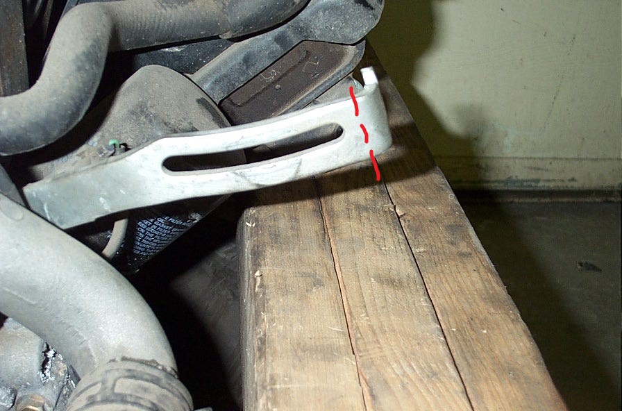
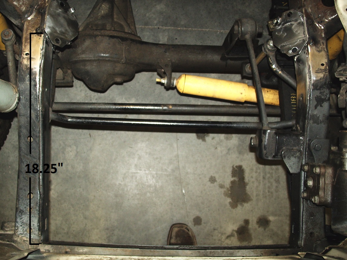
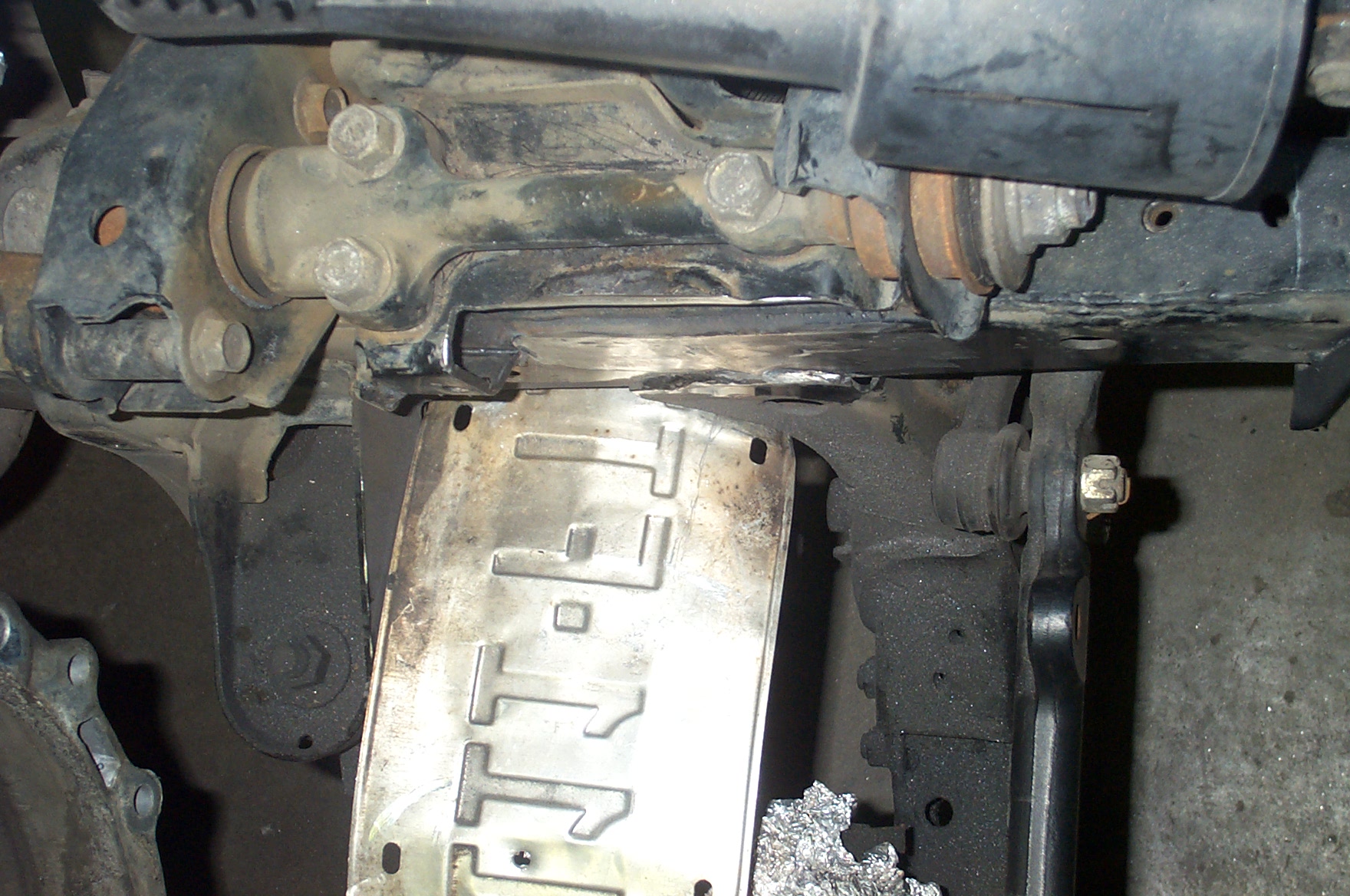
- Make reference marks on the top of the frame that are 18.25” from the front inner corner of the front-frame cross-member (see illustration). NOTE: If using an ‘88-‘95 3VZ transmission/transfer case with cross-member on an ‘84-‘85 frame, 18.5” on the LH side and 18.25” on the RH side may work best. See pic #20
-
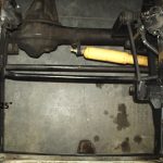
- Pic 20 – Measurements for ORS-EC041 79-85 Bracket Set
-
- The ORS 5VZ frame brackets are not side specific. Place the frame mount brackets on top of the frame. Align the front flat edges of the ORS brackets (where they meet top of frame rail) with the marks.
- Firmly tack-weld the frame-mount brackets in place. Ensure that the front flat edges of the brackets are still aligned with the marks that were made.
- With the frame mount brackets firmly tack-welded in place, test fit the engine. Set the engine on the brackets and tighten using the original engine mount hardware. Be sure the transmission is mated to the engine, as the engine pitch has a big effect on firewall clearance. For safety, be sure the engine remains mounted to the hoist during the entire process (in case the tack welds fail).
- Using whatever methods necessary, be sure that the engine and exhaust will clear the firewall and components on the firewall, the fan will clear the radiator, and the oil pan will clear the suspension and steering. Check any other clearances that may be important.
- Remove the engine and make any adjustments necessary for proper engine fit, install engine to check clearance again if needed.
- Fully weld the frame mount brackets in place. Clean, primer and paint all bare metal.
’86-’95 4×4 Truck/4Runner w/ 22R Engine (ORS-EC041)
NOTE: These frame mount brackets are intended for 4×4 models with the upper control arm mount intact, on the top of the frame. These brackets are designed to place the drivetrain in the same location as the 3VZ-E (3.0L) drivetrain. These frame mount brackets are designed for use with 1991-1995 3.0L 3VZ-E Truck/4Runner engine block brackets, mounted to the 3.4L 5VZ-FE engine block. If a solid-axle swap has been done, the original upper control arm mounts must still be in place, on top of the frame, to use these brackets.
- Locate the original 22R frame mount brackets that are welded to the frame. These brackets are placed at the front end of the upper control-arm frame mounts (assembly over the top of the frame that the upper control arm mounts to), and span down to the top of the frame rail.
- Remove the engine’s frame mount brackets. Leave the frame rail and upper control-arm mounts intact. Smooth the surface with an appropriate grinder or sander.
- Clean the paint from the top and inside of the upper control arm mount assemblies.
- Place the ORS frame mount bracket on top of the upper control arm mount (they are not side-specific). The center of the forward hole in the engine mount should be 11/16” rear-ward of the forward edge of the upper control arm frame mount. SEE PIC #21
-
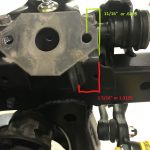
- Pic 21 – Measurement for ORS-EC041 86-95 Brackets
-
- With the ORS frame mount bracket squared on the upper control arm frame mount, tack-weld the bracket in place. Ensure that the center of the forward hole is still 11/16” from the forward edge of the upper control arm frame mount.
- Repeat the last 2 steps on the other side.
- With the ORS frame mount brackets tack-welded in place, test fit the engine. Set the engine on the new brackets and tighten, using the original engine mount hardware. For safety, be sure the engine remains mounted to the hoist during the entire process; in case tack welds fail.
- Using whatever methods necessary, be sure that the engine and exhaust will clear the firewall, the fan will clear the radiator, and the oil pan will clear the suspension. Check any other clearances that may be important.
- Remove the engine and make any adjustments necessary for proper engine fit, install engine to check clearance again if needed.
- Fully weld the ORS frame mount brackets in place. Clean, primer and paint all bare metal.

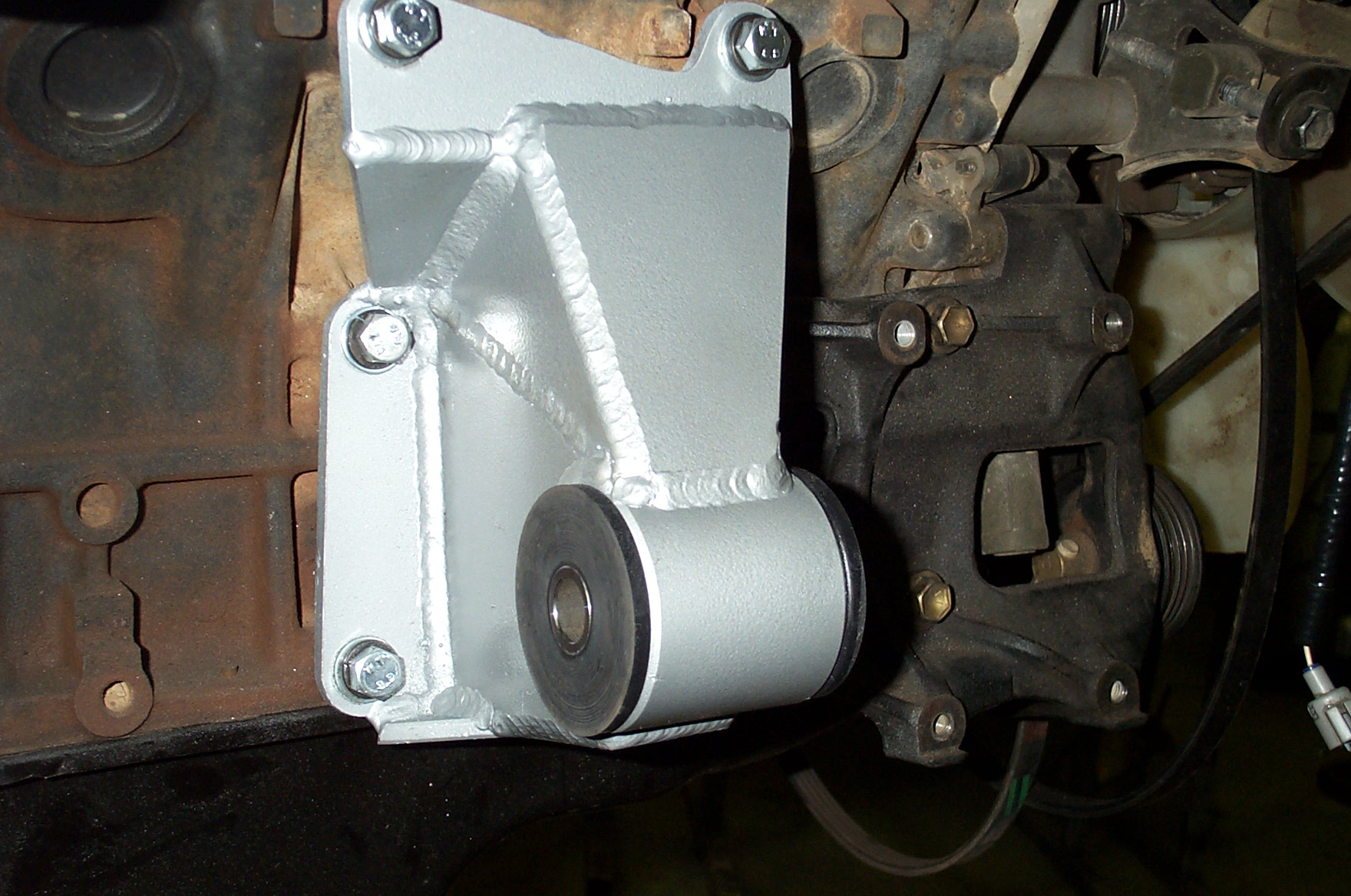
ORS 5VZ-FE Performance Engine Mounts (ORS-EC071)
These mounts are a performance option and completely replace the OEM mounts and brackets.
NOTICE TO INSTALLER: The final fit of the engine is the sole responsibility of the installer. The installer is responsible for test fitting the engine prior to fully welding these mounts to the vehicle frame. If there is a problem with the engine mounts, it must be addressed with Off Road Solutions prior to welding. Read and fully understand these instructions before beginning.
NOTE: These engine mounts are designed to place the drivetrain in the same location as the 3.0L 3VZ-E drivetrain. If using a 3.0L transmission and transfer case, a transmission cross-member from a 3VZ application (or aftermarket) will be needed; the 22R version will not work. This cross-member can also be fabricated. If using a 3.0L transmission and transfer case, 3.0L drive-lines (drive-shafts) will likely work, if vehicle wheel-base is the same.
This kit includes the following:
- 1 x Driver-side mount
- 1 x Passenger-side mount
- 2 x 2” Polyurethane Bushing Set w/ Sleeve
- 2 x 5/8” x 4.5” bolt w/ flat washers, lock washer and nut
- 1 x 10mm x 1.25 x 40mm bolt
- 10 x 10mm x 1.25 x 20mm bolt
- 1 x 10mm x 1.25 x 45mm bolt
- 11 x 10mm flat washer
- 3 x 10mm flat washer (for spacing)
- 11 x 10mm lock washer
- These mounts are built from mild steel. We highly recommend painting or powder-coating (before installation) to prevent rust.
- Install each engine block x mount bolt w/ 1 flat washer and one lock washer under each bolt head.
- Most ’99 and older models: On the RH side mount, front middle hole; install the 3 extra flat washers between the mount and A/C bracket, using the stock bolt and no washers (if applicable). Use the longer provided bolt on the lower front hole in the RH side mount. If no A/C bracket is present, install additional 10mm washers (or a spacer) between the engine block and mounts in this location.
- Most ’00 and newer models: On the RH side mount, front middle hole; the A/C bracket must be trimmed for the mount to fit beneath. Using a sander or grinder, carefully trim .070” (about 1/16”) from the bottom side of the hole-boss until the performance mount fits properly under the bracket, and the A/C bracket fits flush against the engine block at all mounting points. Use the longer provided bolt on the lower front hole in the RH side mount. If no A/C bracket is present, install the additional 10mm washers between the block and performance mount in this location.
- On all blocks, if no A/C is present, use the provided 10mm x 20mm bolt w/ washers in the P/S mount, front middle hole.
- If application-specific frame brackets were purchased (sold separately), some trimming may have to be done to these brackets for a proper fit. Note: to level the engine, the passenger side mounting holes will be roughly 1/2” higher than the driver side mounting holes.
- Take the time to ensure that all clearances are proper when tack-welding the frame brackets. Watch for oil pan x steering/suspension clearance, firewall clearance, radiator x fan clearance, square to vehicle, etc. Be sure to check all these clearances BEFORE FULLY WELDING.
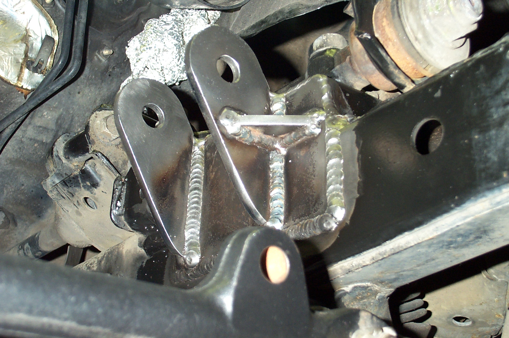
- Note: Once installation is complete, the tab setup on the frame only allows the engine to be removed straight upwards. This means that either the mounts will have to be unbolted from the engine block, or the transmission will have to be removed before the engine is removed. See pics #22 & 23
-
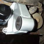
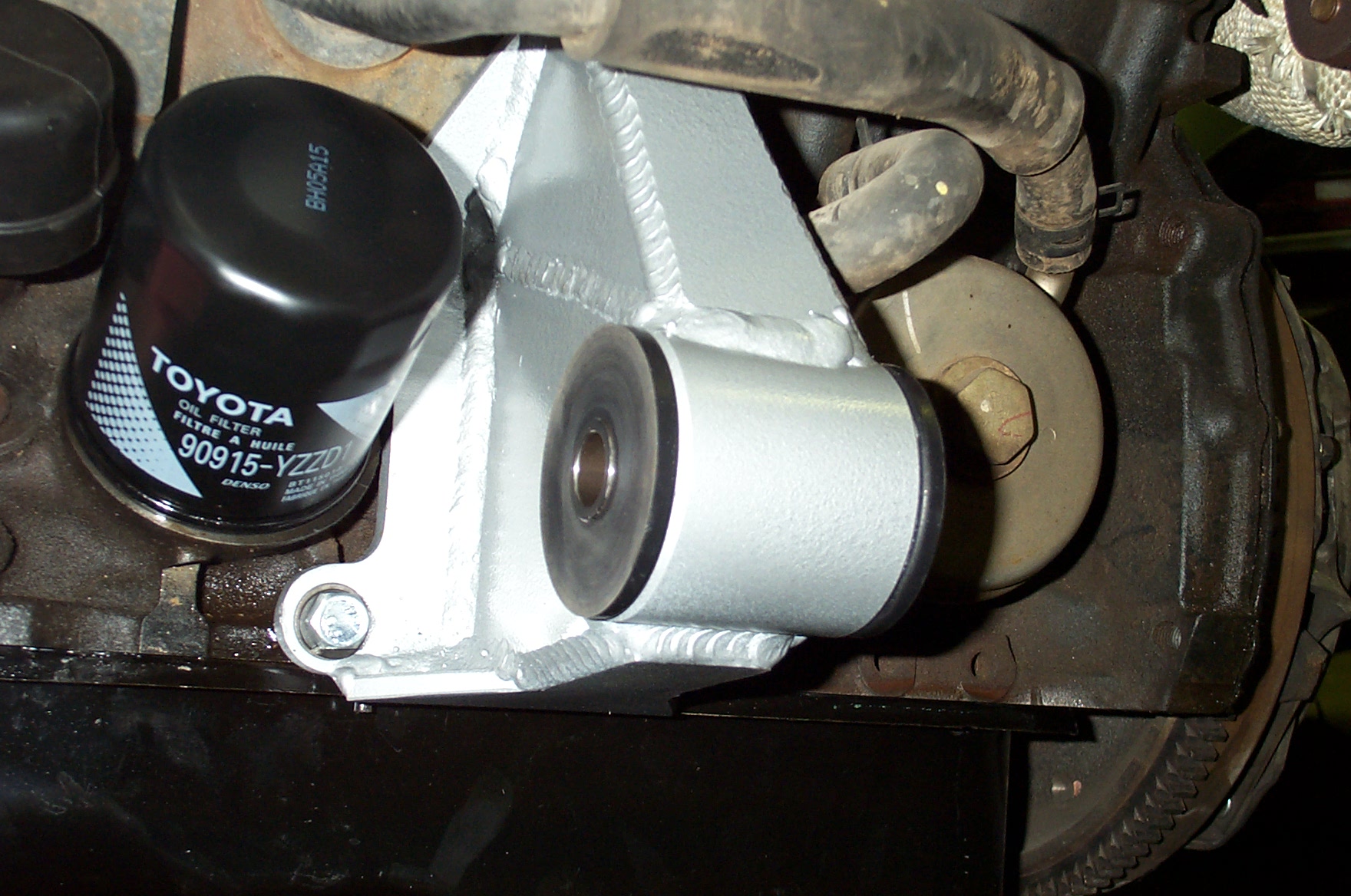
- Pic 22 – Performance Mount, LH
-
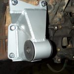
- Pic 23 – Performance Mount, RH
-
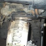
Performance Engine Mount Frame Bracket Set, ’86-’95 4×4 IFS Frame (ORS-EC073)
This is a frame-bracket set, specifically for the performance engine mounts.
This kit should include the following:
- 2x Frame plate, large
- 2x Frame plate, small
- 2x Tab, longer
- 2x Tab, shorter
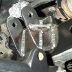
- This installation should be done w/ the engine out of the vehicle. Be sure to shield all components from cutting/welding debris.
- The Upper Control Arm (UCA) mounts must first be trimmed to accommodate the new frame plates. This trimming will be parallel with the side of the frame. The provided frame plates make a good template for trimming. See pic #24.
-
- Pic 24 – UCA mount clearance for performance mount frame tab
-
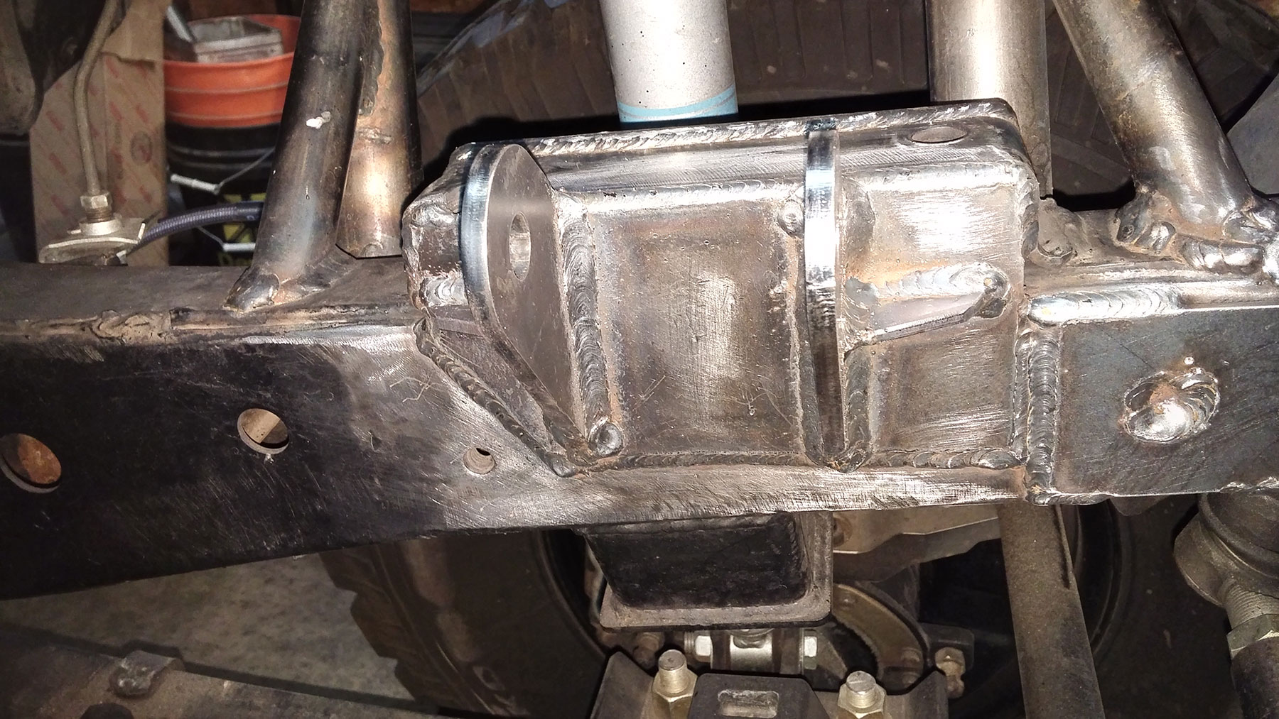
- Weld the provided plates into place. The large plate will be against the frame and cover most of the created “hole”. The smaller plate will be perpendicular at the rear end of the larger plate, covering a smaller hole. See pics #25 & 25a
-
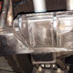
- Pic 25 – Performance mount frame bracket installed
-
- Pic 25a – Performance mount frame bracket installed
-
- Bolt the mount tabs to the engine mounts (already on engine). The passenger (RH) side will use the longer tabs. Place 1 thin washer between the mount and 1 tab. This will provide some needed “working” space to remove/install the engine once the tabs are welded.
- Set the engine into the engine bay. Temporarily bolt the transmission to the engine.
- Check clearance against the oil pan, steering, exhaust, firewall, heater valve, radiator/fan, etc. Adjust as necessary and tack-weld the tabs to the frame plates. Carefully check all these clearances again.
- Carefully remove the engine. Now that the tabs are fixed to the frame the transmission may have to be removed first, or the mounts removed from the engine block. Shield all components.
- Install spacers (stacked washers work well) snugly between the tabs to simulate the engine mount width. Install a bolt through the tabs and lightly tighten. Fully weld the tabs to the frame plates. Add a gusset to the front tab if desired. See illustration above.
- Clean and paint the bracket area.
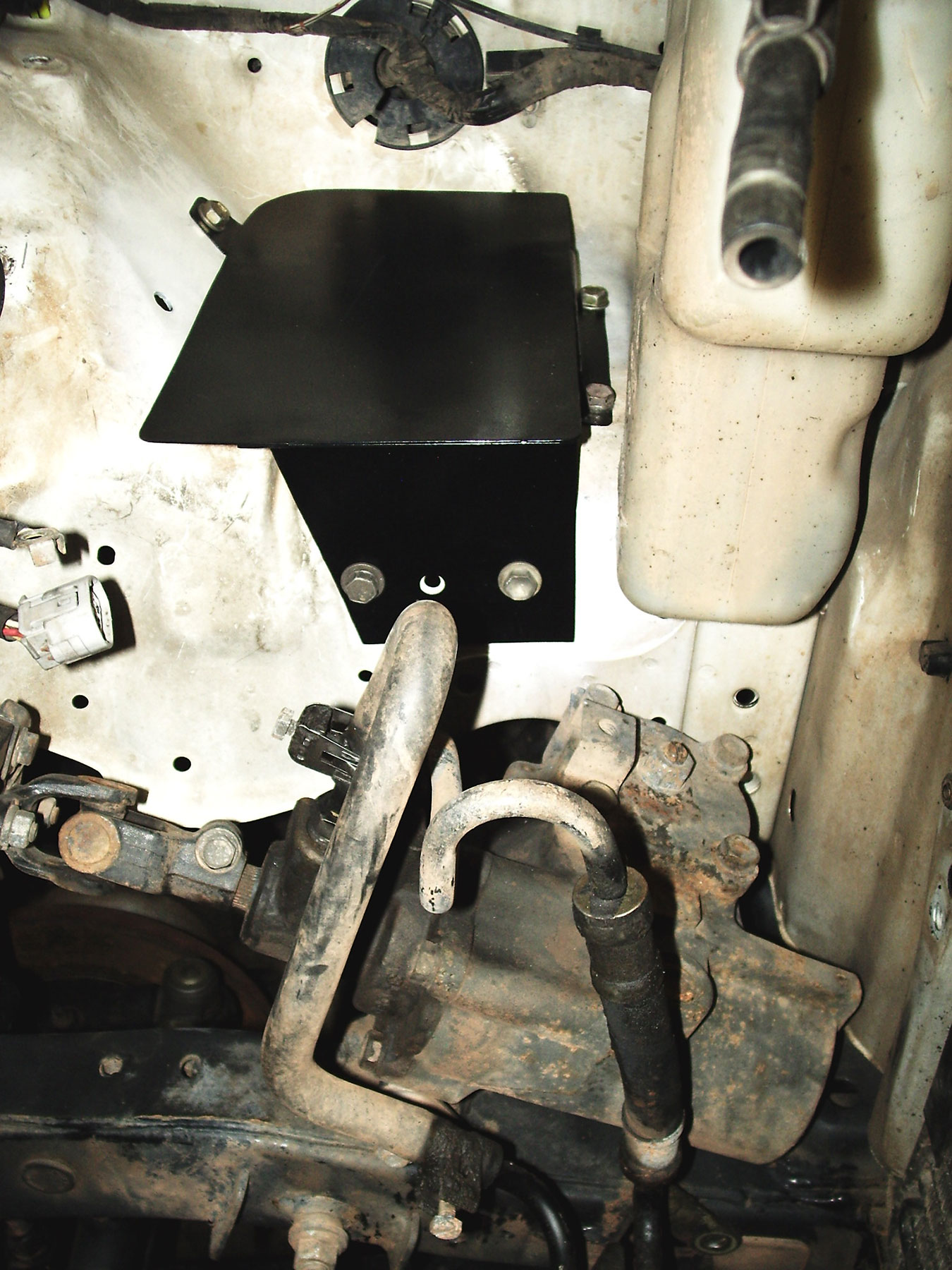
Battery Mounting
Since the 5VZ intake is pointed to the RH side of the engine bay, moving the battery from the RH front corner of the engine bay makes the new intake system install easier. The ORS battery tray and fuse box extension cable are meant to facilitate this by moving the battery to the other side of the engine bay. Other options include moving the battery to the rear of the vehicle or building a short intake system and leaving the battery in the RH front position.
Battery Relocation Tray (ORS-EC030/EC040)
- This tray is delivered un-painted and is constructed of mild steel. We recommend painting this tray prior to installation.
- Remove the washer bottle and any other restrictions in LH front corner of the engine bay.
- Set the ORS Battery Relocation Tray in this corner. Using the washer bottle (will be used in it’s stock location) and battery as a guide, find the best location to install the tray. Also be sure to verify hood clearance to the top of the battery.
- Clamp the tray into place. Using the bolt holes in the tray as a guide, mark the location for holes to be drilled in the fender-well. There will be 1 hole in the rear upper corner, 2 in the front side, and 2-3 in the fender below the tray. Remove the tray and drill the mounting holes in the fender-well.
- Bolt the tray in place using the provided hardware.
- If using the tray w/ a built-in tie-down, the battery will be tied down w/ the provided top strap and fasteners.
- If using the Basic tray (no tie-down provisions), drill an additional hole in the fender, behind the tray. This hole can be used for a J-hook. It is wise to strengthen this hole by adding a large washer behind the opening. Fabricate a tie-down method, or modify the original tie-down strap and J-hook to secure the battery to the tray. This battery tray will not serve its function if the battery is not fastened from the top w/ a tie-down.
See pics #26-28
-
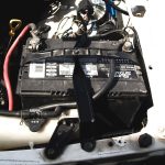
- Pic 26 – Full Battery Tray Installed
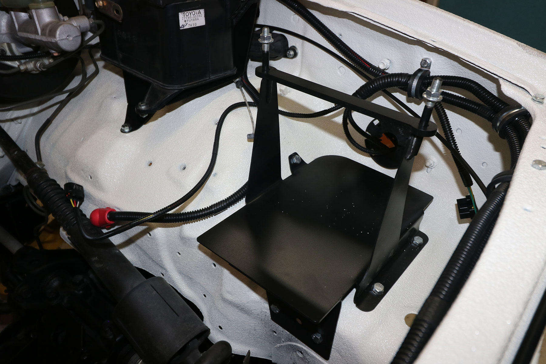
-
- Pic 26a – Full Battery Tray Installed
-
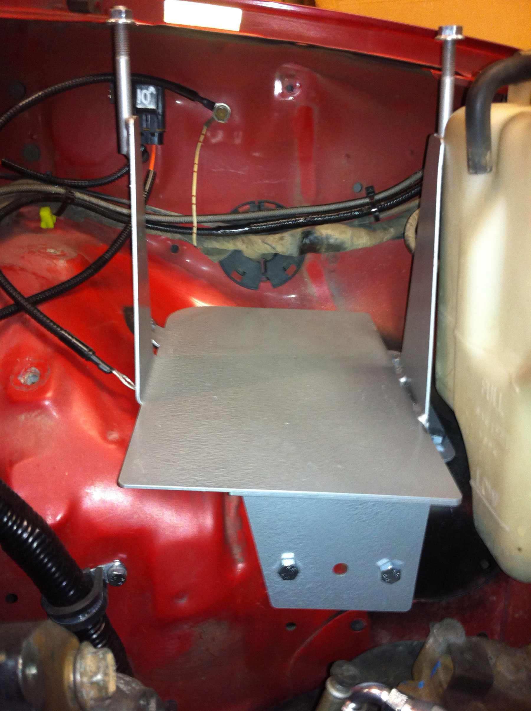
- Pic 27 – Basic Battery Tray installed
-
- Pic 28 – OEM Battery Tie down, modified to work with Basic Battery Tray

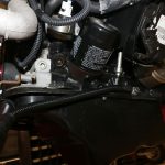
Battery Cables/Connections (ORS-EC046 & ORS-EC047)
The ORS Battery Cable Harness is only needed when the battery is on the LH side of the engine bay and the original battery cable harness (from donor vehicle) is missing/damaged; or when a body lift is installed.
This section applies to battery connections with either the original battery cable harness or the ORS Battery Cable Harness. This section also covers battery connection in general, including the ORS Fuse Box Cable Extension (ORS-EC047).
*****NOTICE TO CUSTOMER: If there is a problem suspected with the wiring harness, call Off Road Solutions. DO NOT cut, alter, or dissect the ORS battery harness. Off Road Solutions accepts no responsibility for a harness that has been tampered with – NO EXCEPTIONS.
There is no warranty on the ORS 3.4L Battery Harness.
- Watch our video to learn more about battery, alternator, and starter wiring.
- This harness is designed to work with a “reverse” terminal battery, installed with the negative terminal on the LH side. Standard terminal batteries can also work, but having the cables reach is a stretch.
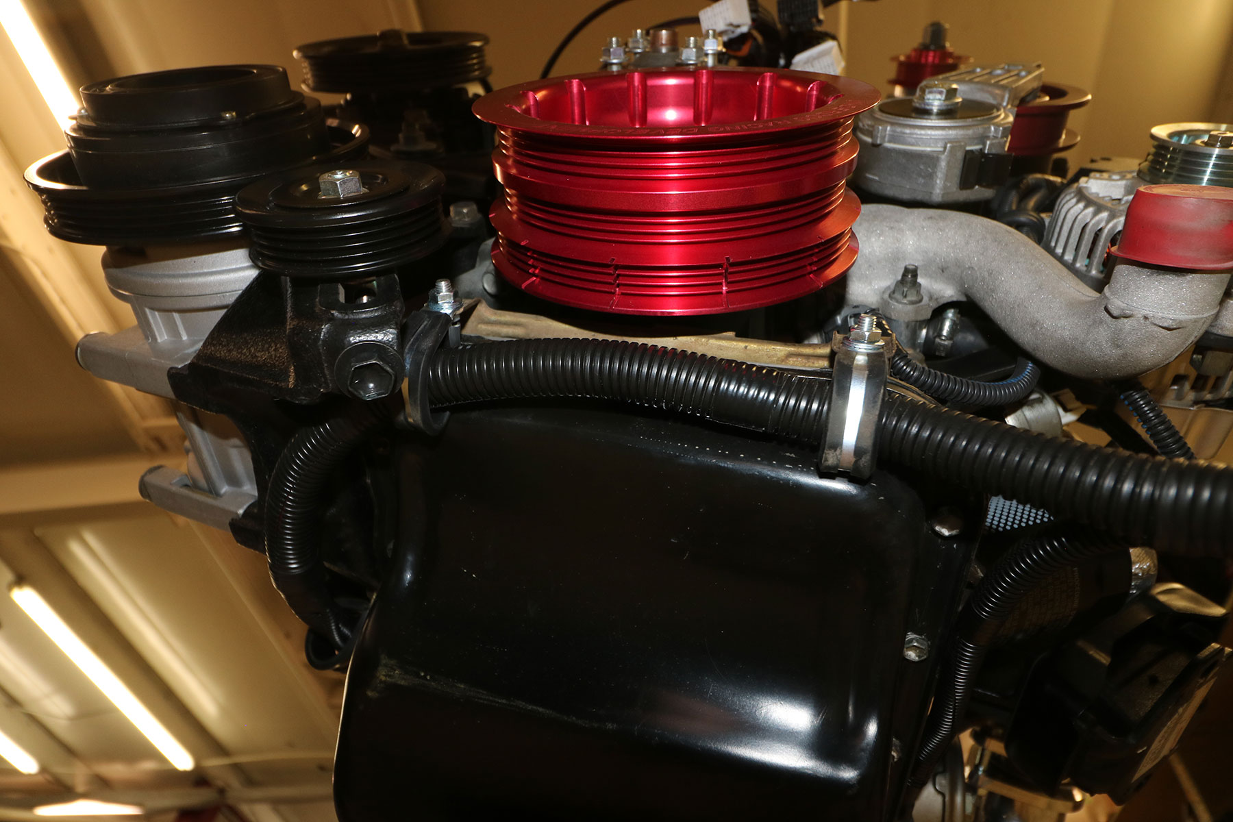
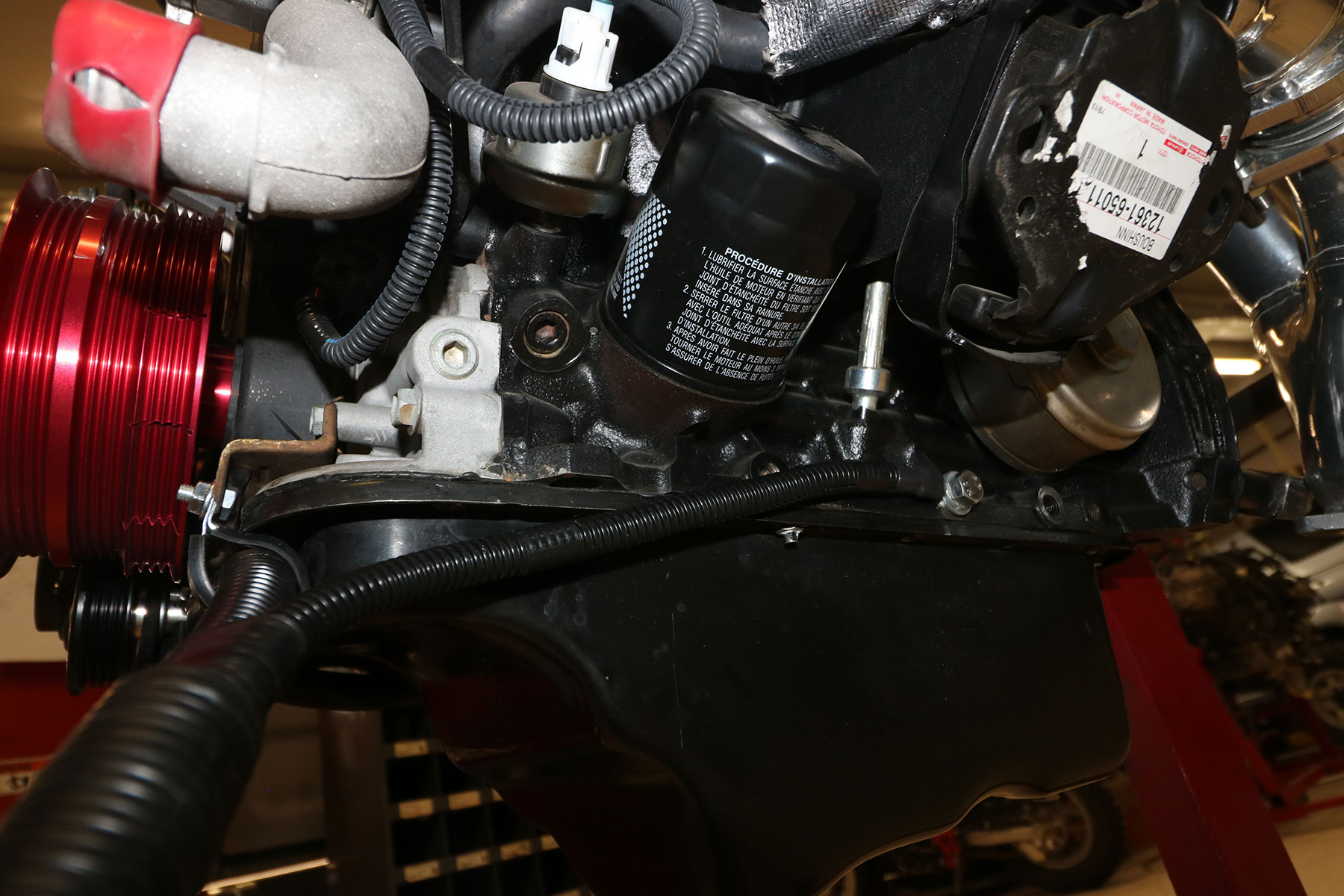
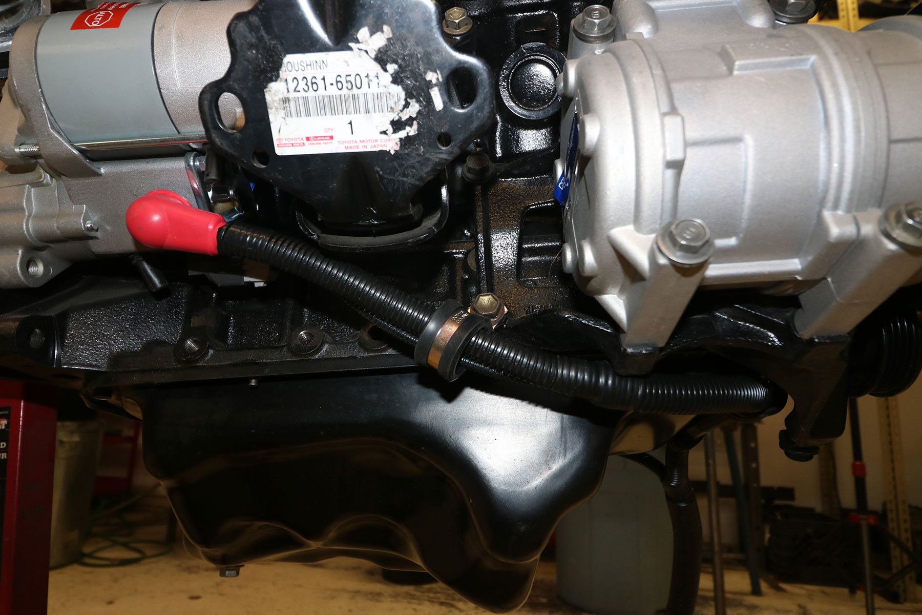
- Route the ORS battery harness along the bottom front of the engine, behind the crankshaft pulley.
- Connect the battery harness to the main starter terminal/post and the starter trigger terminal.
- Fasten the large ground in the battery harness to the lower LH side of the engine block, near the oil filter.
- The original battery harness had a plastic cover that retained the battery harness behind the crankshaft pulley. If available, this can be re-used on the ORS harness in the same configuration. If not, use the provided closed clamps to secure the battery harness to the front of the engine so that it cannot make contact with the crankshaft pulley. Failure to do this properly may result in a fire.
- Route the battery harness under the steering shaft and up the inside of the LH side fender well. Using the provided closed clamps, secure the battery harness to the fender well and frame so that the harness is clear of the steering shaft. Failure to do this properly may result in a fire.
- Connect the positive terminal to the battery.
- The wire from the ORS 3.4L Conversion Harness labeled “to starter trigger” will splice to the wire on the battery harness labeled “to ORS starter trigger lead” (these should both be black wires).
- The ORS Fuse Box Cable Extension (ORS-EC047) is used to connect the main fuse box positive cable to the battery, after the battery is re-located to the LH side. The original fuse box will remain in its original position. Cut the original fuse box positive cable (originally connected to battery positive terminal) about 3” from the original eyelet. The ‘fusible link’ section should now be removed and the remaining cable core should be approximately the same size as the ORS cable core. Making a high quality connection and seal, splice the original fuse box cable to the cut end of the ORS cable.
- Route the ORS Fuse Box Cable Extension to the battery positive terminal. We recommend following and securing to the headlamp harness, in front of the radiator.
- Connect the fuse box power cable (ORS-EC047) and all other positive battery connections to battery positive terminal.
- Check over your installation to be sure the battery harness is not rubbing against any sharp edges or moving parts.
- See Pics 29, 29a, 29b
-
- Pic 29 – Battery Harness installation on engine
-
- Pic 29a – Battery Harness installation on engine
-
- Pic 29b – Battery Harness installation on engine
-
- If an alternator pigtail connector was provided, that will be used during the alternator wiring, later in the process.
Clutch Install, Transmission (ORS-EC058, MAR-MCCL-119, ORS-EC068 – CLUTCH)
- If the transmission is not already installed in the vehicle, install the transmission in vehicle.
- Note: Either a 3.4L (5VZ-FE) or 3.0L (3VZ-E) clutch/flywheel can be used. The 5VZ flywheel is slightly larger, providing more surface area for friction. The flywheel and clutch must be from the same application. Flywheel bolts matching the flywheel application must be used. Using new bolts is also recommended. The release bearing must match the application of the transmission and bell-housing.
- Unless the flywheel is new, we recommend machining the flywheel prior to installation to ensure smooth operation. Clean any oil residue found on flywheel. Install the flywheel on the engine. Apply thread locker to the flywheel bolts and torque to 65 ft-lbs in a “star” pattern. Note: When holding the crankshaft in place, do not use the crankshaft pulley bolt – this could loosen the bolt. We recommend using a flywheel strap on the flywheel or a chain wrench on the front pulley to hold the crankshaft in place.
- As a precaution, check the torque of the front crankshaft pulley mounting bolt. The early versions of the 5VZ were prone to loosening up. The torque spec. is 215 ft-lbs. If this bolt is found loose at all, remove the bolt, apply thread locker and re-install using the specified torque.
- Install the provided pilot bearing into the end of the crankshaft. Check the bearing for smooth operation to ensure proper installation. Clean the friction surface on the flywheel.
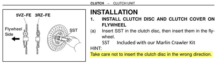
- Using a clutch alignment tool, center the clutch disc on the flywheel. Note: We have found that plastic clutch alignment tools do not always align the clutch disc perfect. Although this is not possible for some, an input shaft from an older Toyota truck transmission, cut off, makes the most accurate alignment tool.
- 5VZ, 3.4L Clutch: The disc springs (raised section) must be facing toward the flywheel – REGARDLESS OF MARKINGS ON THE DISC. SEE IMAGE:
-
- Clutch Disc Installation
-
- 3VZ, 3.0L Clutch: The disc springs (raised section) must be facing away from the flywheel.
- Install the pressure plate onto the flywheel and torque the mounting bolts in a star pattern to 14 ft-lbs.
- Remove the clutch fork from the transmission. Apply a small amount of anti-seize to the ball in the bell housing and the pivot point on the fork. Also apply a thin coat to the prongs that engage the release bearing. Clean the input shaft cover and apply a thin coat of wheel bearing grease to the cover (where release bearing slides). Also apply a thin coat of grease to the input shaft splines.
- Install the clutch fork in the transmission with the provided release bearing. Be sure that all mounting clips are secure.
Engine Install
- Check the mating surfaces on the engine block and transmission bell-housing for dowel pins. There should be two dowel pins in the engine block and no dowel pins in the transmission.
- Carefully lower the 5VZ engine into the vehicle. Align the engine with the transmission and place in the engine mounts. Re-use the engine mount-to-frame hardware from the 3VZ or 5VZ engine. Re-use the bell-housing bolts from the transmission application.
- Install the stiffening plates (optional, side of block to lower bell-housing) from the 3VZ to the 5VZ engine in the same place and secure the original mounting hardware in the block and bell housing.
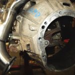
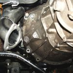
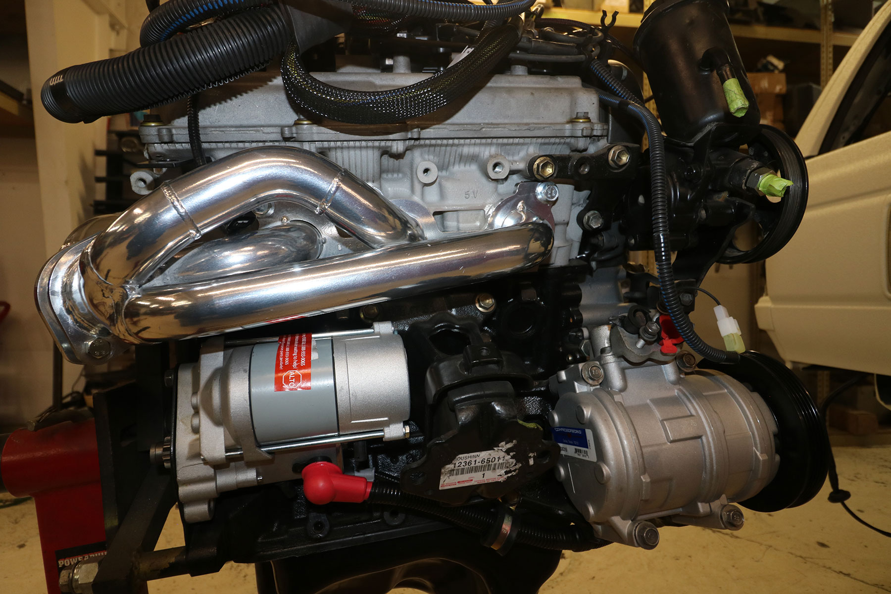
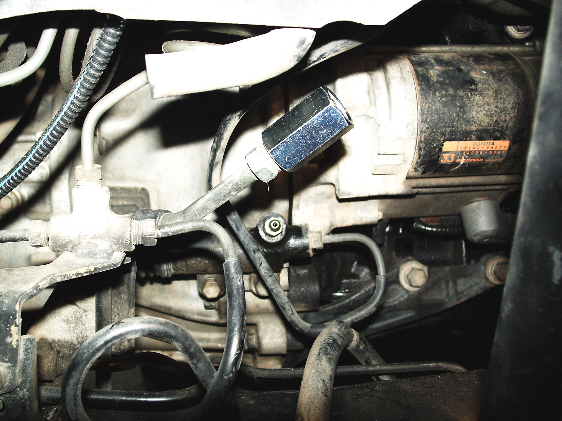
- Install the starter. If using the 3VZ transmission, either a 3VZ or 5VZ starter can be used. If using a 5VZ starter, modify the 5VZ starter to fit the 3VZ bell-housing. Carefully drill the LOWER mounting hole in the 5VZ starter with a 7/16” bit. Clean any metal particles from the starter. See pics # 30 & 30a
-
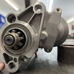
- Pic 30 – 5VZ starter with lower hole drilled, for use with 3VZ transmission
-
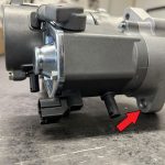
- Pic 30a – Pic 30 – 5VZ starter with lower hole drilled, for use with 3VZ transmission
-
- If using a 5VZ transmission, a 5VZ starter will be required.
- Manual-Transmission: Connect the clutch hydraulic system. For RH-slave cylinder: Install the clutch slave cylinder, hard line to bracket on engine, then hose to the bracket on the firewall.
- If using the ORS Header Set, we recommend the use of our RH-slave clutch hose for header, which will bypass the header pipe. This will install between clutch bracket on the firewall and the slave cylnder. Secure the hose to the inner fender using the provided clamp. See Pic #10
-
- Pic 10 – Clutch hose for RH-slave cylinder
-
- For LH-slave cylinder, install the ORS LH-clutch hose between the master cylinder and the slave cylinder. Secure the hose to the inner fender using the provided clamp. See pic #31
-
- Pic 31 – Clutch hose installed for LH-slave cylinder
-

Shifter Installation – IF Using Donor A340F/E Automatic Transmission
- Place the new shifter assembly in Park position. Lay the shifter assembly on the floor and match the shifter to the reference mark taken with the original shifter in place. In most cases, the new shifter will line up with a few original mounting holes. The shifter location does not have to exactly match, but we recommend that it is within ½” of the original location.
- With the shifter in place, mark the floorboard for any trimming that may have to be done for the transmission and transfer case shifters to function. Also take note of any sheet-metal that may have to be added to cover any unnecessary holes in the floorboard. Mark the holes that do not line up with the body for drilling.
- Remove the shifter assembly and do any trimming or patching necessary. Be sure to paint any bare metal and seal any open seams. Drill the marked holes for shifter mounting.
- Place the transmission shifter back in place. Install the shifter. Bolt down the shifter assembly using the new holes and the existing holes.
- Install the new transfer case shifter. Slight bending of the shifter may be necessary for clearance against the transmission shifter. If bending the shifter is necessary, be sure to support the base of so that the portion that drops into the transfer case is not bent or tampered with.
- Use the original transfer case shifter-boot or the shifter-boot from the donor vehicle to seal the floorboard. Drill the necessary holes and mount the shifter-boot to the floorboard.
- Place the transmission shifter and the transmission itself in the park position. Locate the shift rod from the original vehicle. From under the vehicle, reference the proper length of the shift rod by measuring from the floorboard shift lever to the transmission shift lever.
- Take note of the position of the 2 ends of the shift rod in relation to each other. Loosen the adjuster bolts, center the adjustment on the shift rod, and tighten adjuster bolts.
- Measure the length of the shift rod. Compare this to the necessary length and cut the necessary amount from the tubing section of the shift rod to achieve the proper length. Reference the brackets at the ends of the shift rod so they are “clocked” in the proper position in relation to one another.
- Weld the shift rod back together. Paint the shift rod.
- Using the original hardware, install the shift rod. Loosen the adjusting bolts on the shift rod and make any final adjustments necessary to ensure the both the transmission shifter and the floor shifter are firmly in the park position.
- From inside the vehicle, check that the shifter moves through all positions properly.
- See pic #32
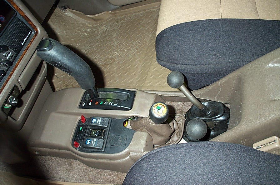
-
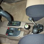
- Pic 32 – Donor shifter installed in recipient interior, Auto-Transmission
-
Under-Hood Assembly
Heater Hose Installation (ORS-EC054, EC055, EC056, EC057)
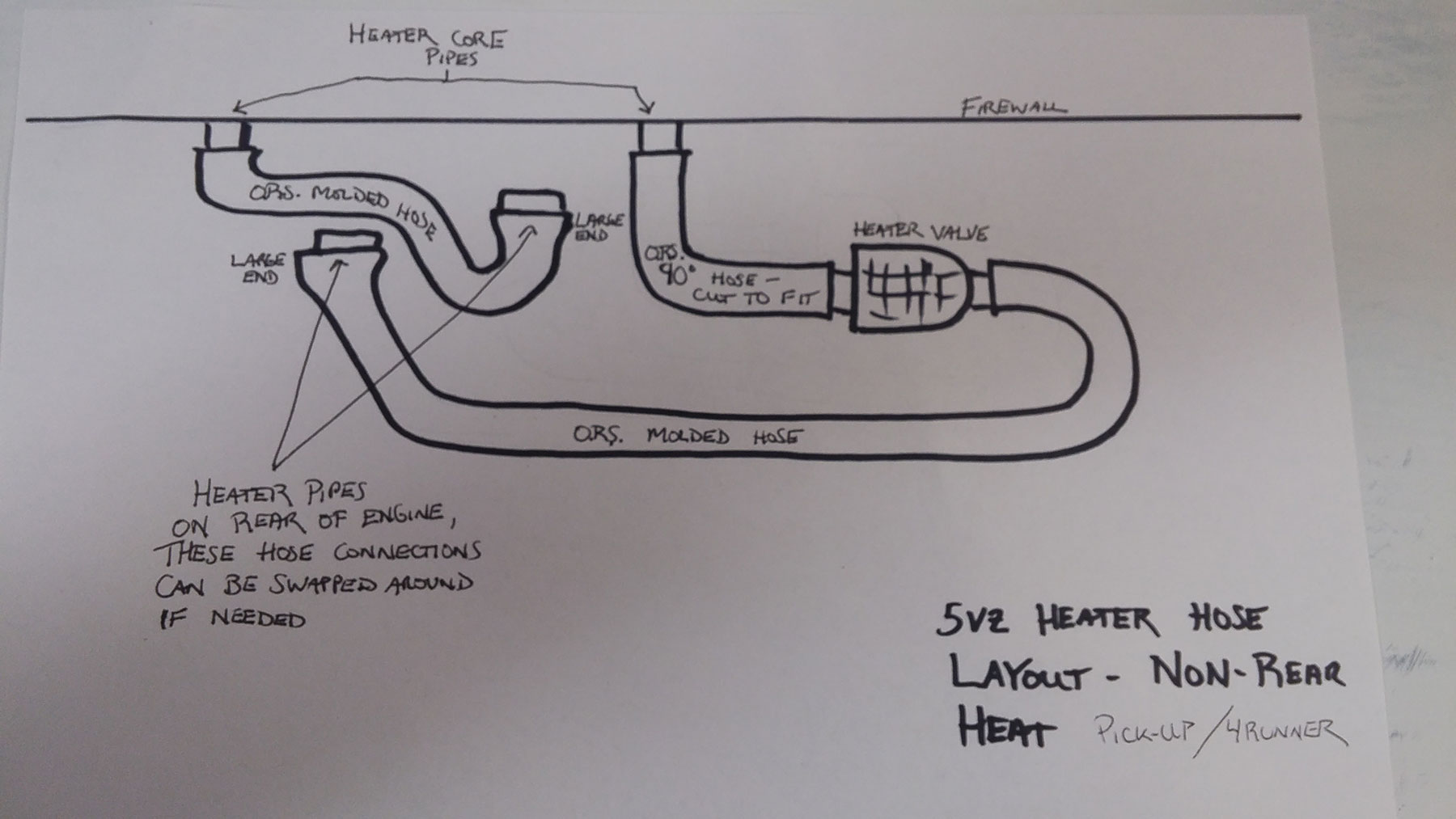
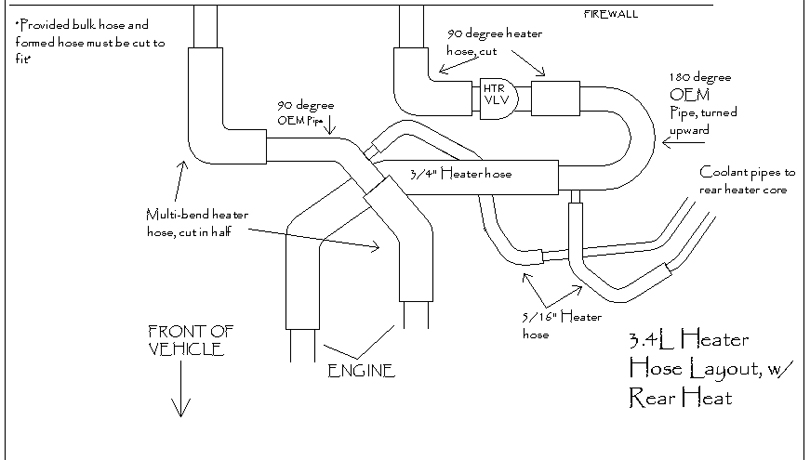
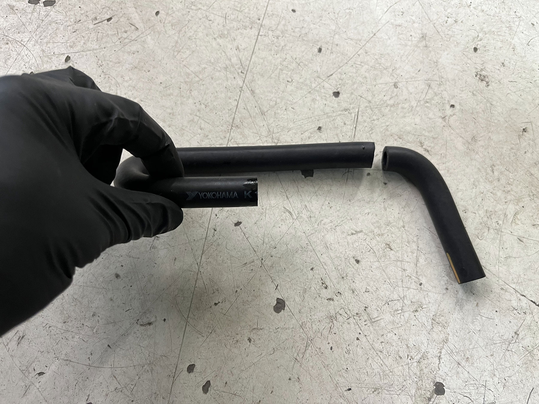
Install heater hoses. If using an ORS Cooling/Heater Hose kit, the provided 90-degree hose will require trimming on both ends to fit. Install heater hoses on the rear of the engine following the illustrations. Clamp hoses in place. See illustrations, pics #33 & 34
-
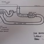
- Pic 33 – Heater Hose Layout, w/out rear heat
-
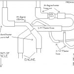
- Pic 34 – Heater hose layout, WITH rear heat
Fuel Hoses (ORS-EC033, EC034, EC035, EC035A)
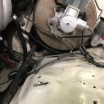
Note: The original 22R-E or 3VZ-E fuel pump (in-tank) normally works well with the 5VZ engine and can be left in place. However, if forced induction is used, ORS recommends upgrading to a performance fuel pump. Trucks or 4Runners originally equipped with fuel injection have a fuel pump mounted inside the fuel tank and a high-pressure fuel line from the tank to the engine bay area.
Carbureted vehicles do not have a high-pressure system in place. In this case, we recommend installing a fuel tank and hard line from a similar-vintage vehicle that had the 22R-E or 3VZ-E. When not using a Toyota tank w/ internal fuel pump, we recommend installing a high-pressure fuel pump in the existing fuel tank/fuel cell. The fuel cools the fuel pump during operation, helping it last longer. Additionally, in-tank fuel pumps nearly eliminate the risk of ‘vapor lock’ in the fuel system. If an external (in-line) fuel pump is used, we recommend mounting it as close to the tank as possible and as low as safely possible.
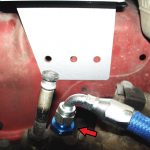
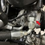
- The original fuel supply line (high pressure hard-line from fuel tank/pump) enters the engine bay on the RH-side frame rail (on fuel injected models).
- At this end of the line, there is either a male fitting (nut), a female fitting, or a female to female fitting (union) fastened to a male fitting. A female fitting or a union is necessary. If needed (male fitting only), this fitting can be found through Toyota or ORS, PN 90404-14014. See pic #35
-
- Pic 35 – Union installed for fuel hose
-
ORS High Pressure Fuel Hose
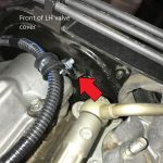
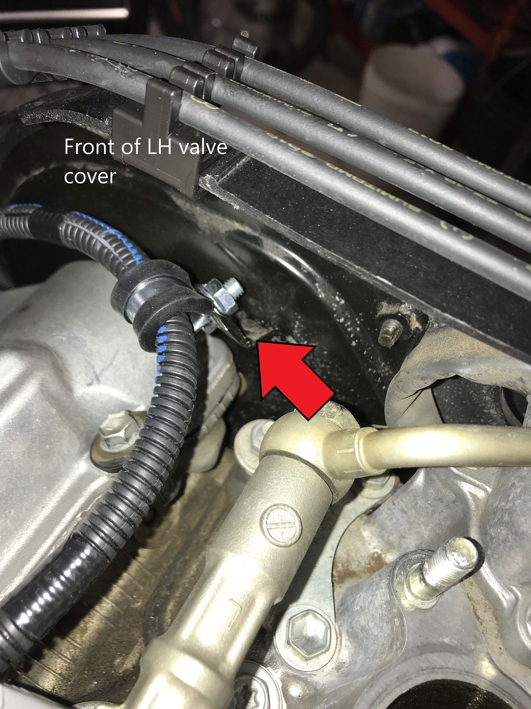
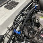
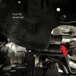
- Full Hose and Hose with Filter: Remove the original 3.4L high pressure fuel hose from the rear of the fuel rail and discard. This will require removing the bolt and clip fastening the engine harness to the rear of the engine, then moving the engine harness up and to the rear. Install the provided banjo adapter in place of the original hose fitting, at the rear of the RH fuel rail, using the provided gaskets and original banjo bolt. See pic #36
-
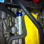
- Pic 36 – Fuel Banjo Installed on Fuel Rail
-
- Install the provided M-M adapter into the F fitting/union on the original fuel supply line. Note the orientation of the adapter, it is a compression fitting with different threads at each end. Tighten both adapters.
- Fuel Hose Extension: Install the remaining M-M adapter into the end of the existing 5VZ fuel hose. Note the orientation of the adapter, it is a compression fitting with different threads on either end. Tighten the adapter.
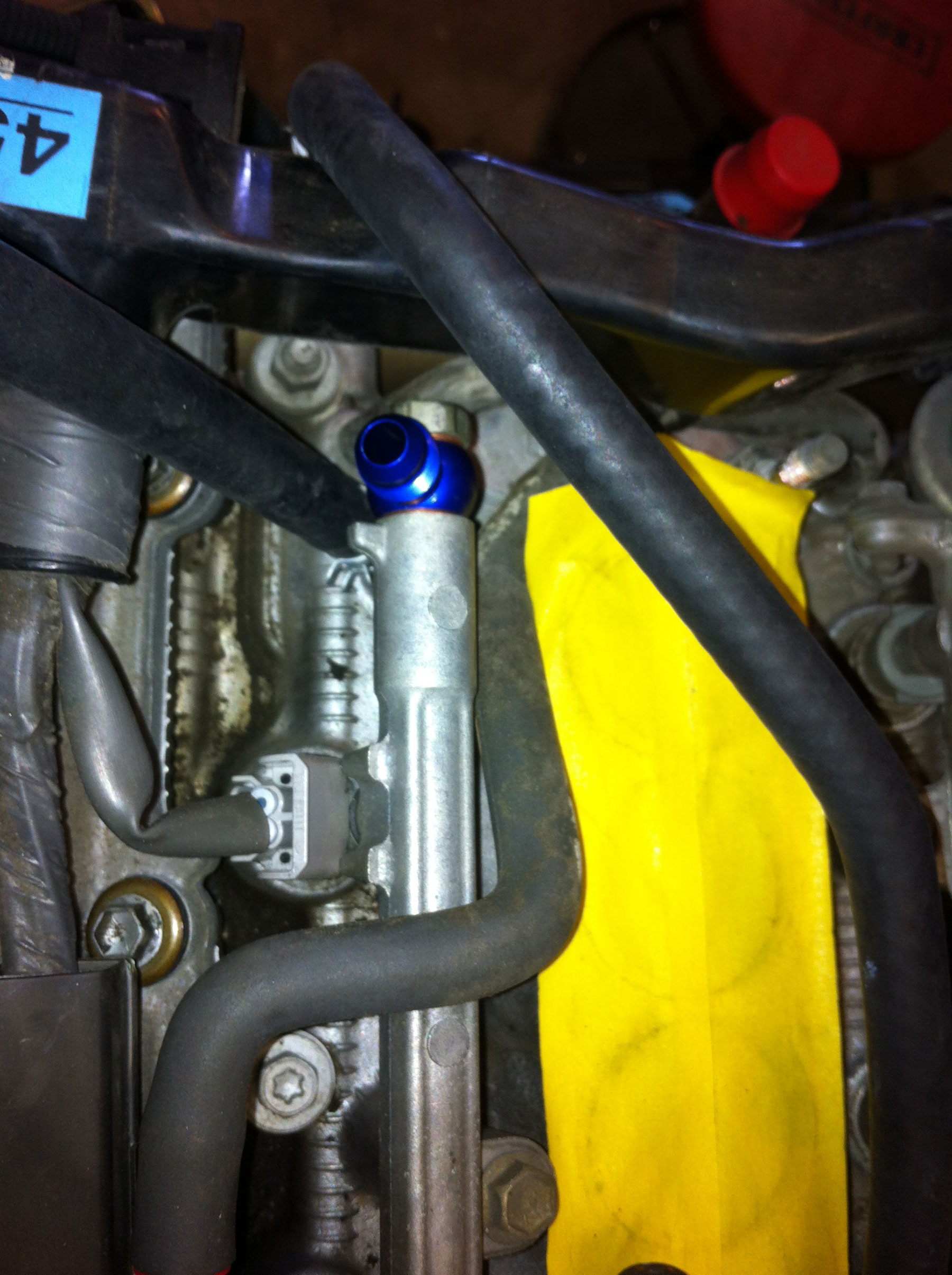
- Hose with Filter: Using the provided clamp, mount the fuel filter on the inner fender above the fuel supply line. Note filter orientation by the inscription on the filter. The shorter hose will be used between the frame supply line and filter, use this as a guide when mounting filter, see pic #37
-

- Pic 37 – Fuel Filter Installed on High-Pressure Fuel Hose
-
- 7th Injector-Ready Fuel Hose: The installation of this hose at the engine and fuel line is the same as the full hose. There is an extra section of hose that will route to the new 7th injector. The adapter on the 7th injector must be replaced with the provided Adapter. We recommend using thread tape on the threads into the new injector on the provided adapter. See pic #38
-
- Pic 38 – 7th-Injector version of High Pressure Fuel Hose
-
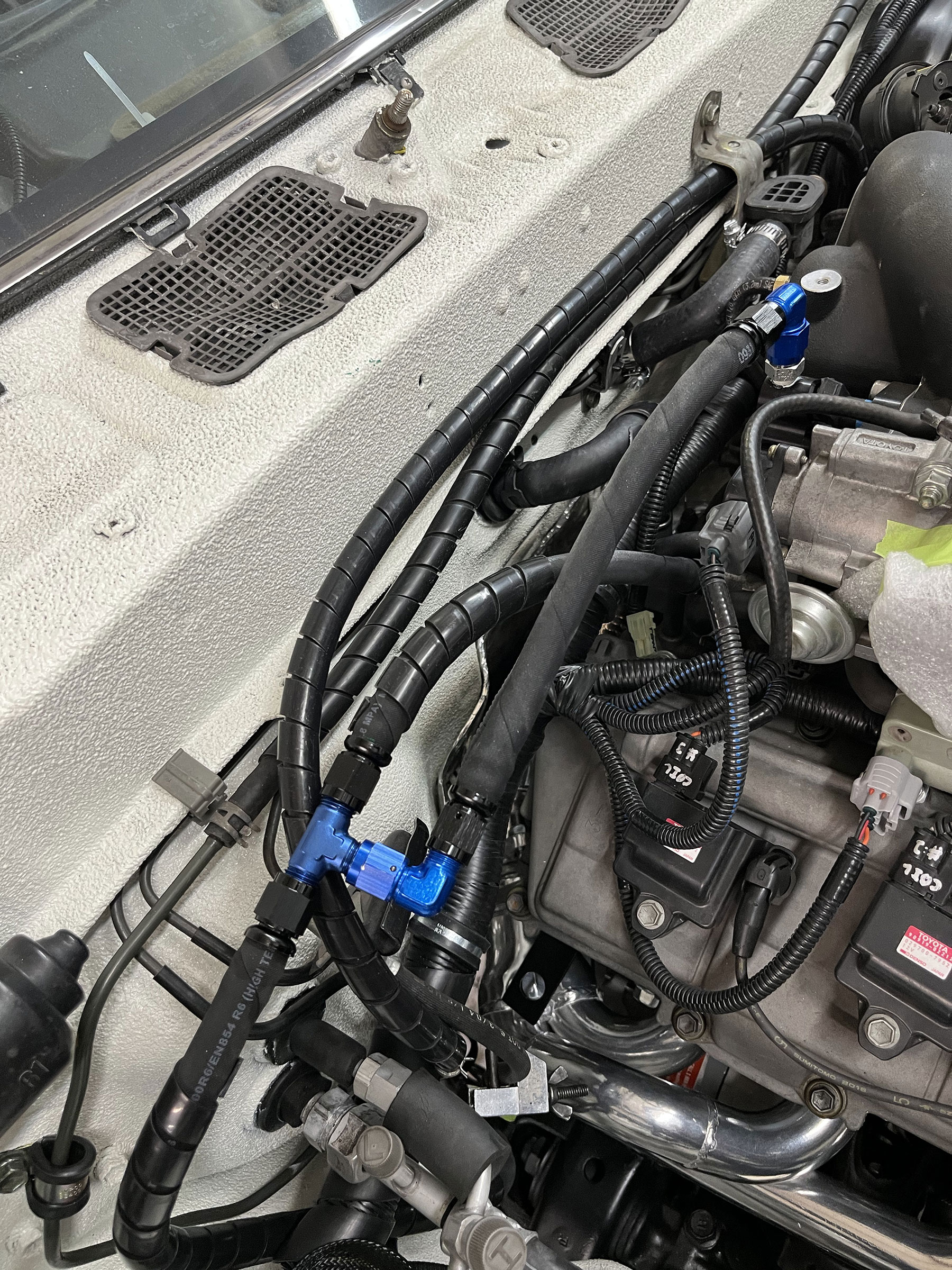
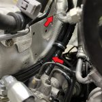
- Route and install the ORS High Pressure Fuel Hose(s) between the adapters (and filter if applicable), tighten all fittings. See pic #39
-
- Pic 39 – Fuel Hose Routing at firewall
-
Note: If a 5VZ fuel hose was previously installed and the 7th Injector kit is now being added to the engine: Install the provided hose section and adapter to the new 7th Injector. This hose section will now be spliced to the existing ORS fuel hose. Using the new hose length (and pic #38) as a guide, cut the existing hose and press the two ends of the existing hose onto the new 7th Injector section. Caution: This will only work with relatively new hose, in good condition. If using an older hose, we recommend a complete replacement.
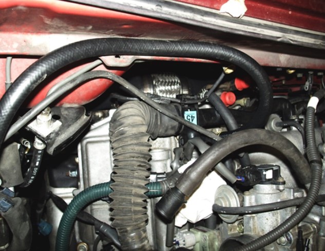
Fuel Return Hose:
The original 5VZ fuel return hose started at the fuel pressure regulator (rear LH fuel rail), was then routed a short distance to a hard line. That hard line traveled from the rear LH corner of the engine and around the LH side of the intake plenum.
- Start the fuel return hose routing at the hard line under intake plenum, or the fuel pressure regulator on the LH fuel rail. From there, route the fuel return hose across the engine bay (along the firewall) to the original fuel return line on the firewall, near the RH rear side of engine. Using hose clamps, secure the return hose at both ends. If this hose was not purchased through ORS, 1/4” fuel injection hose works well.
Power Steering Hose (ORS-EC031, EC032, EC048)
Models originally equipped with the 3VZ engine do not require a new or custom high-pressure power steering hose. The original HP PS hose can be re-used if it is in good condition. To do this, simply re-use the original banjo bolt and the original-style gasket into the new pump. We have found that the idle-up valve (part of the 5VZ PS pump fitting) can be removed from the system during this engine conversion, this is not needed.
For models originally equipped with the 22R/22R-E engine or those with a 3VZ HP PS hose in poor condition, the ORS High Pressure Power Steering Hose is useful.
The ORS High-Pressure Power-Steering Hose will not fit 4×2 Cab/Chassis (inc. RV) models, the steering gear is different. An OEM replacement hose is recommended on these models.
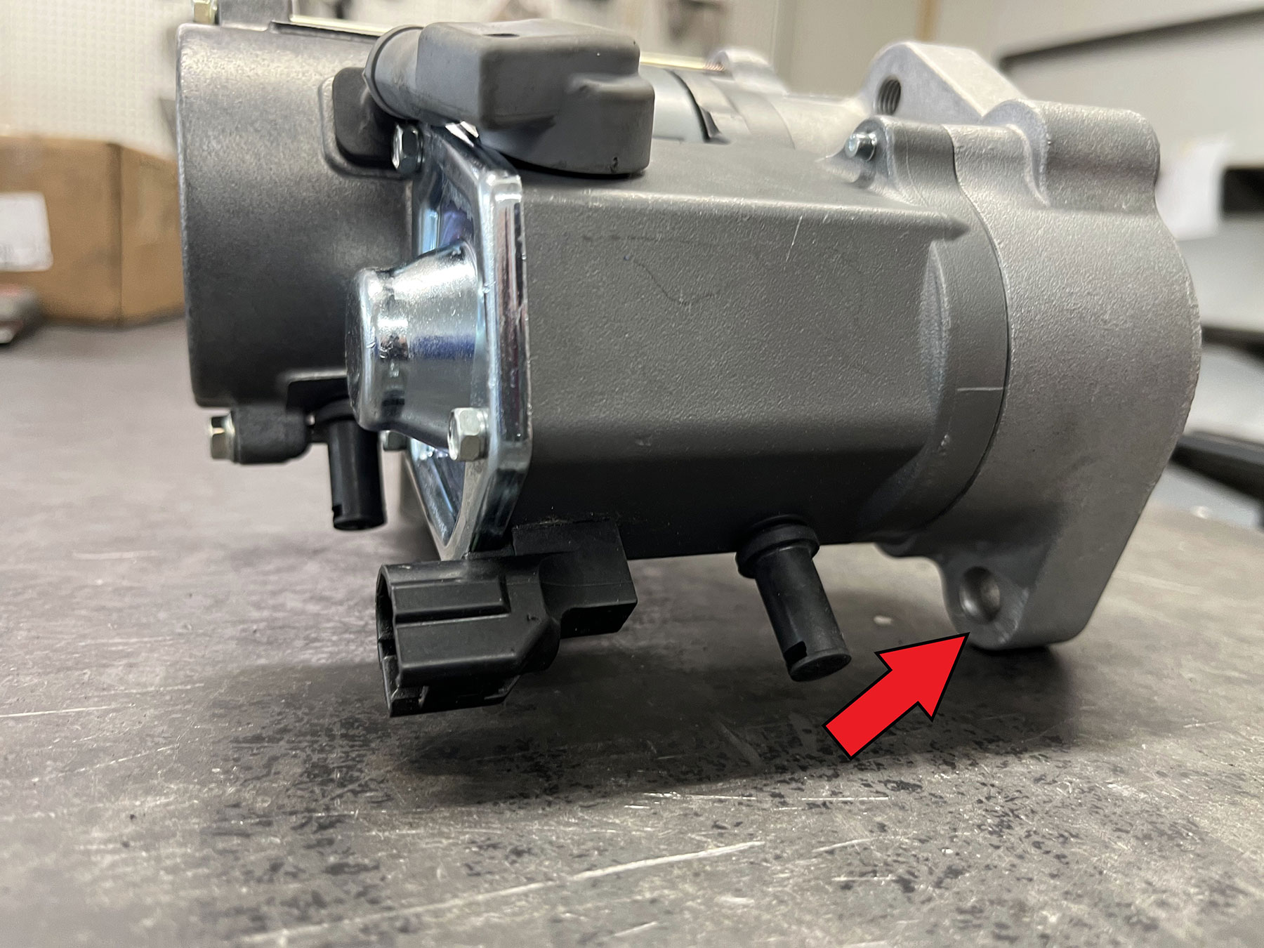
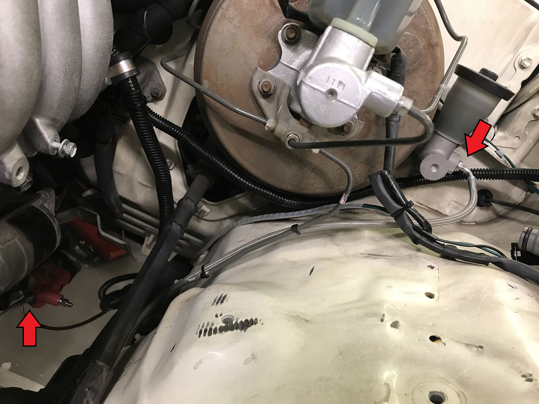
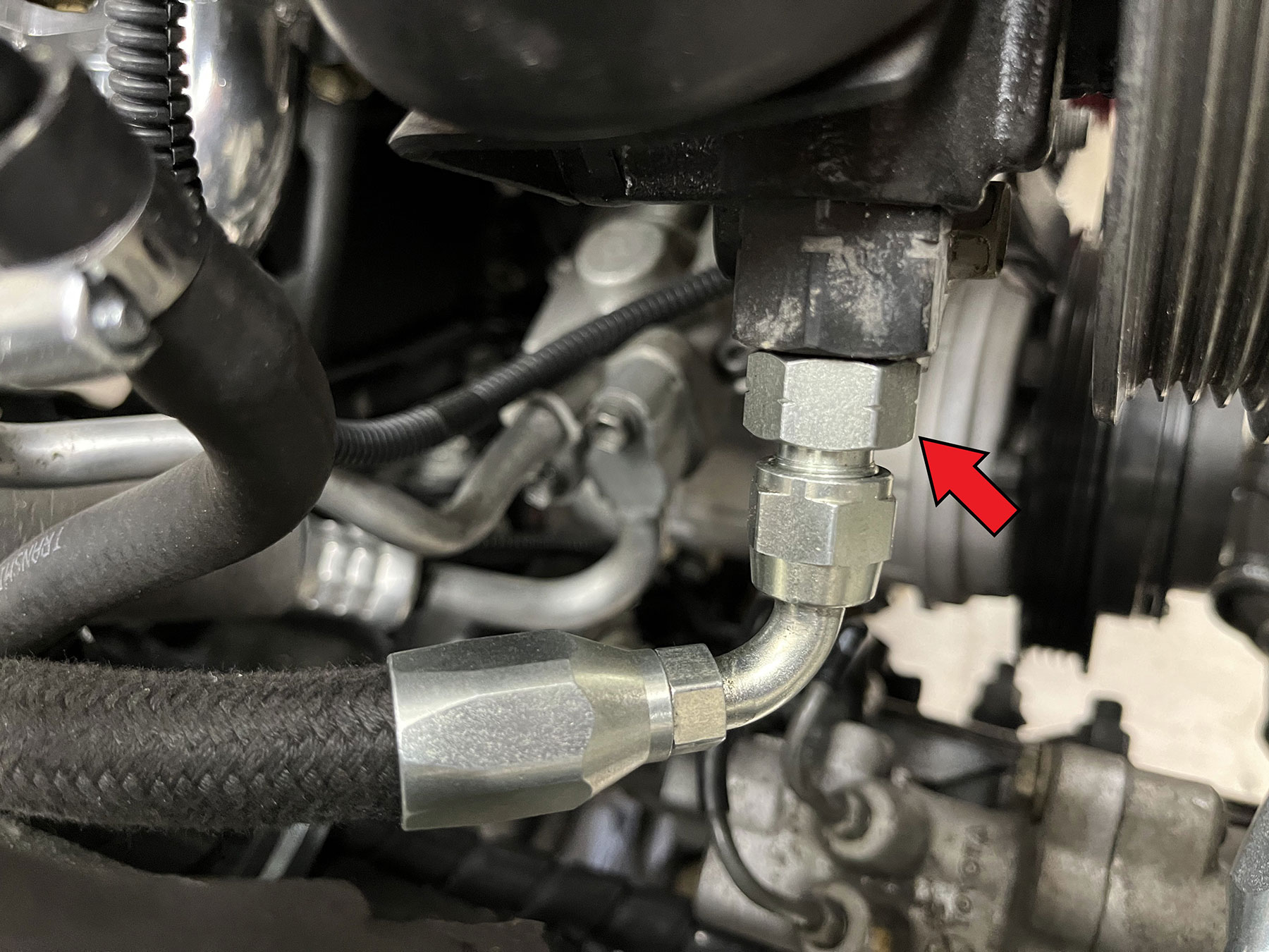
- Install one adapter into the steering gear or the ABS actuator (if equipped). With the ABS actuator, the provided gasket is installed between the adapter and the ABS actuator as a seal. If installing the adapter into the steering gear, be sure the gold-colored compression fitting is in place, inside the steering gear port. Tighten the adapter. See pic #40a
-
- Pic 40a – Adapter installed at PS Pump, PS Gear
-
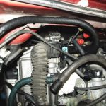
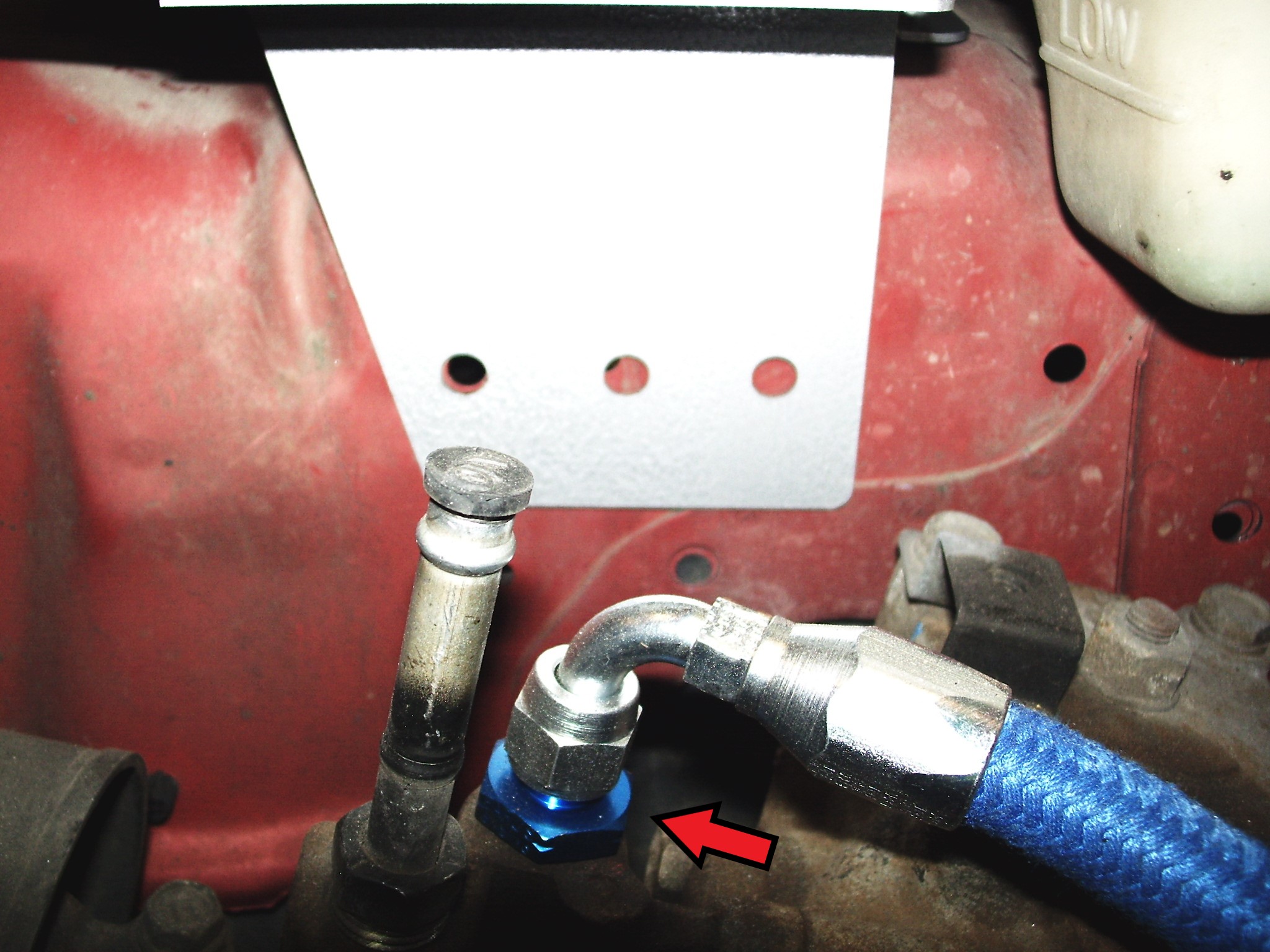
- Install the other adapter into the high pressure port of the power steering pump. Make sure the gold-colored compression fitting is in place, inside the pump port. Tighten the adapter. See pic #40
-
- Pic 40 – Adapter installed at PS Pump
-
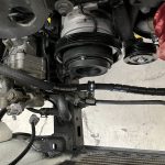
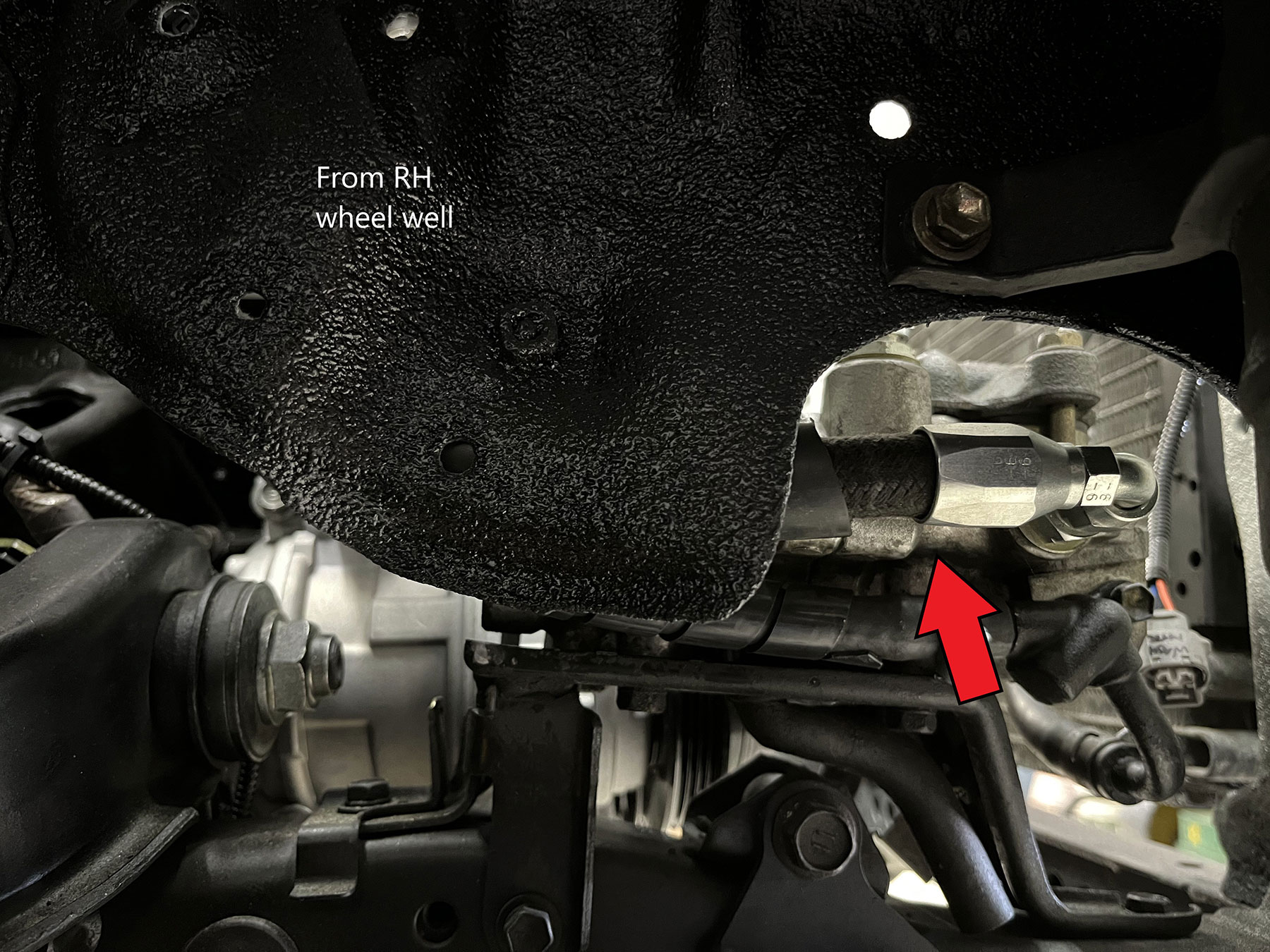
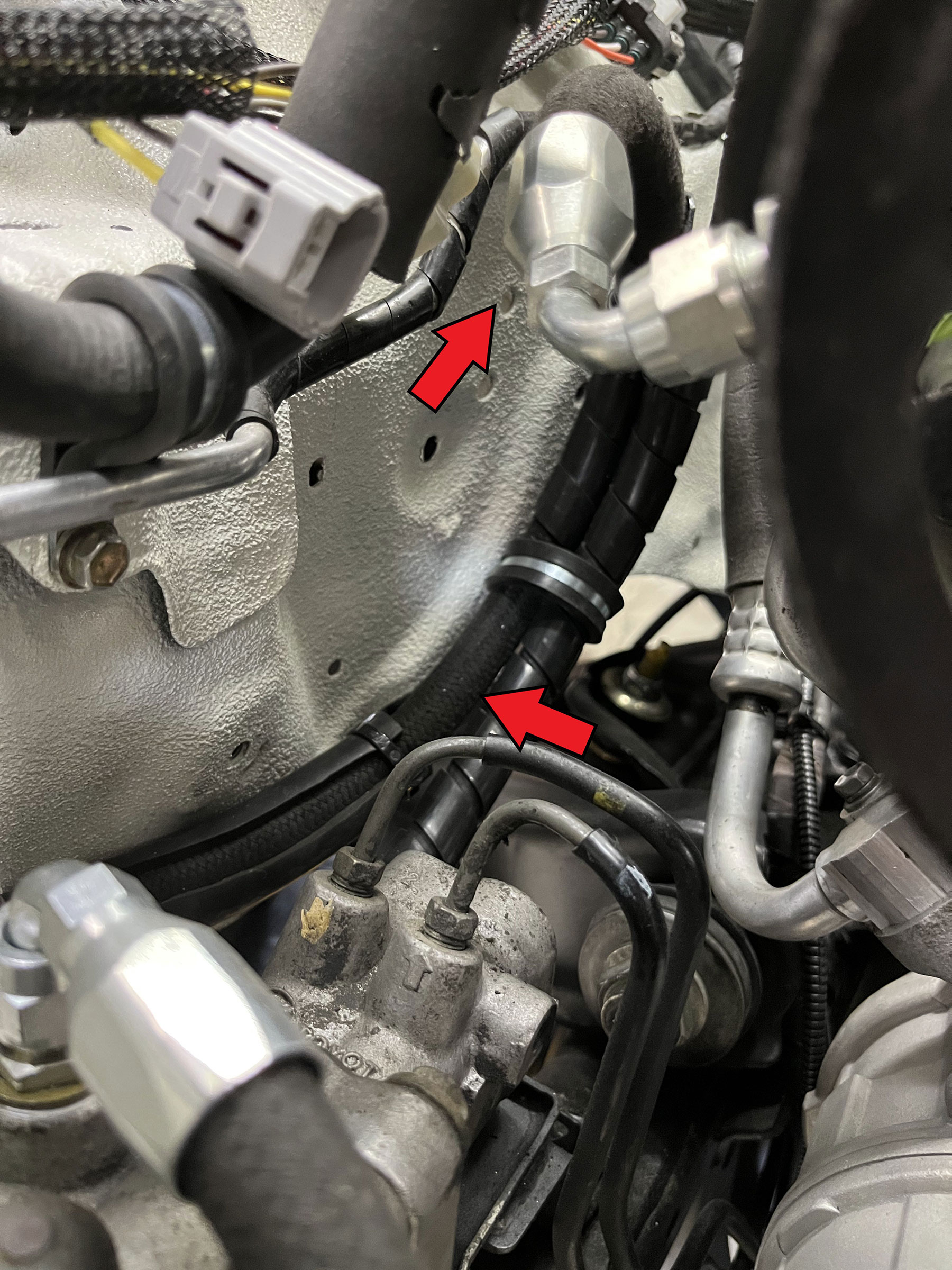
- With ‘Non-ABS’ hoses, the 45 degree fitting is the pump end of the hose. Route the high-pressure power-steering hose from the pump, under the fan shroud, to the steering gear.
- With ‘ABS’ hoses, route the hose from the P/S pump toward the rear of the vehicle, then bend the hose to a “U-shape” and route the other end down to the ABS actuator. See pics #42 42a
-
- Pic 42- PS High Pressure Hose (w/ RW ABS) Installed
-
- Pic 42a- PS High Pressure Hose (w/ RW ABS) Installed
-
- Install the hose onto the adapters and tighten, see pics 40 & 40a
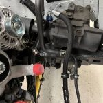
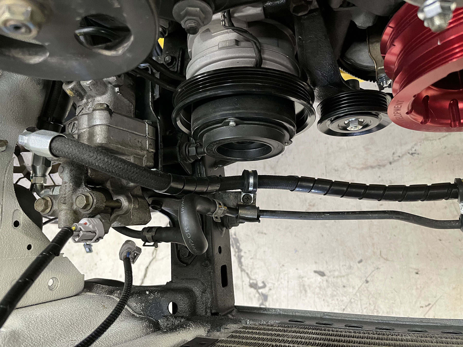
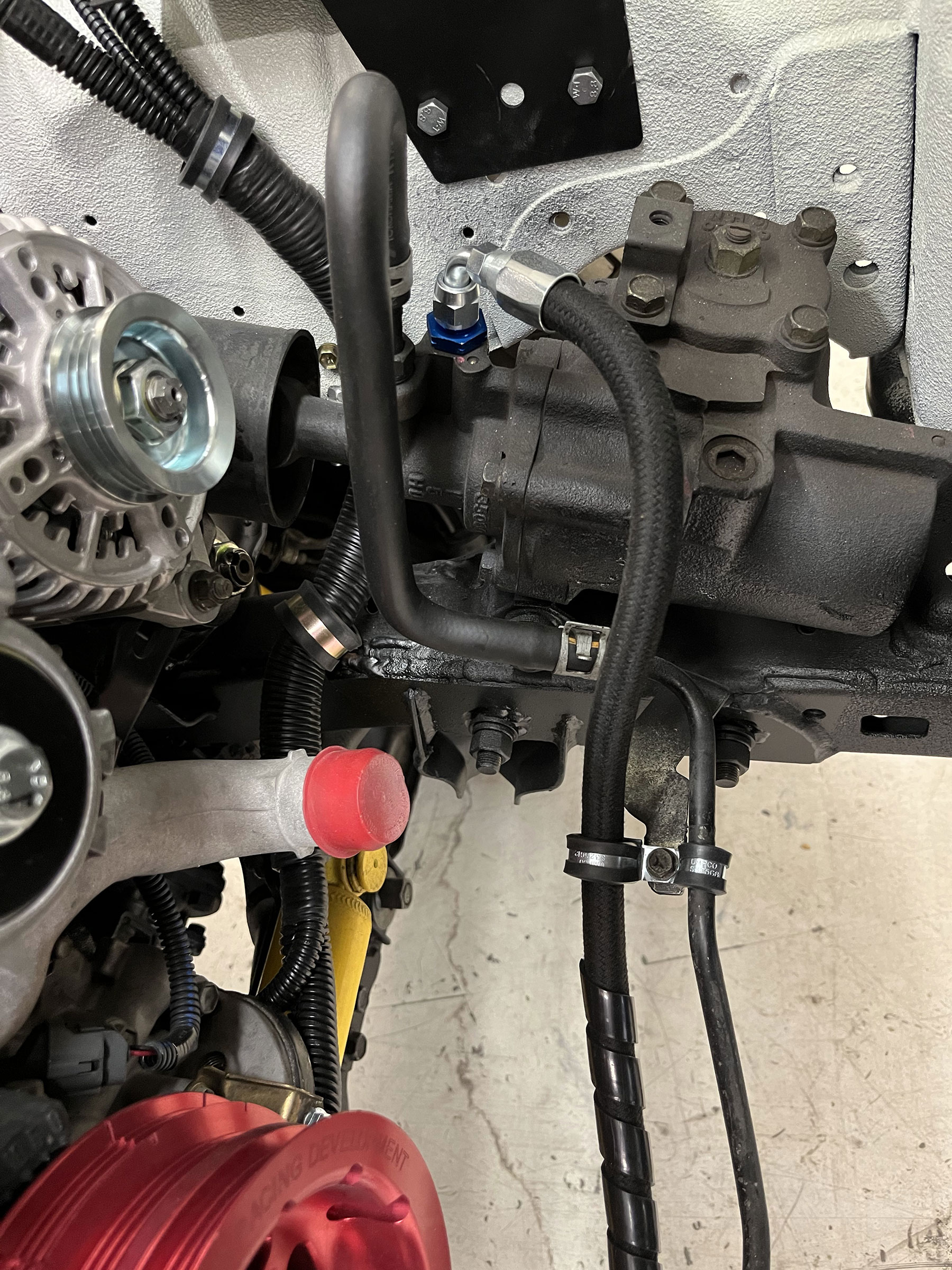
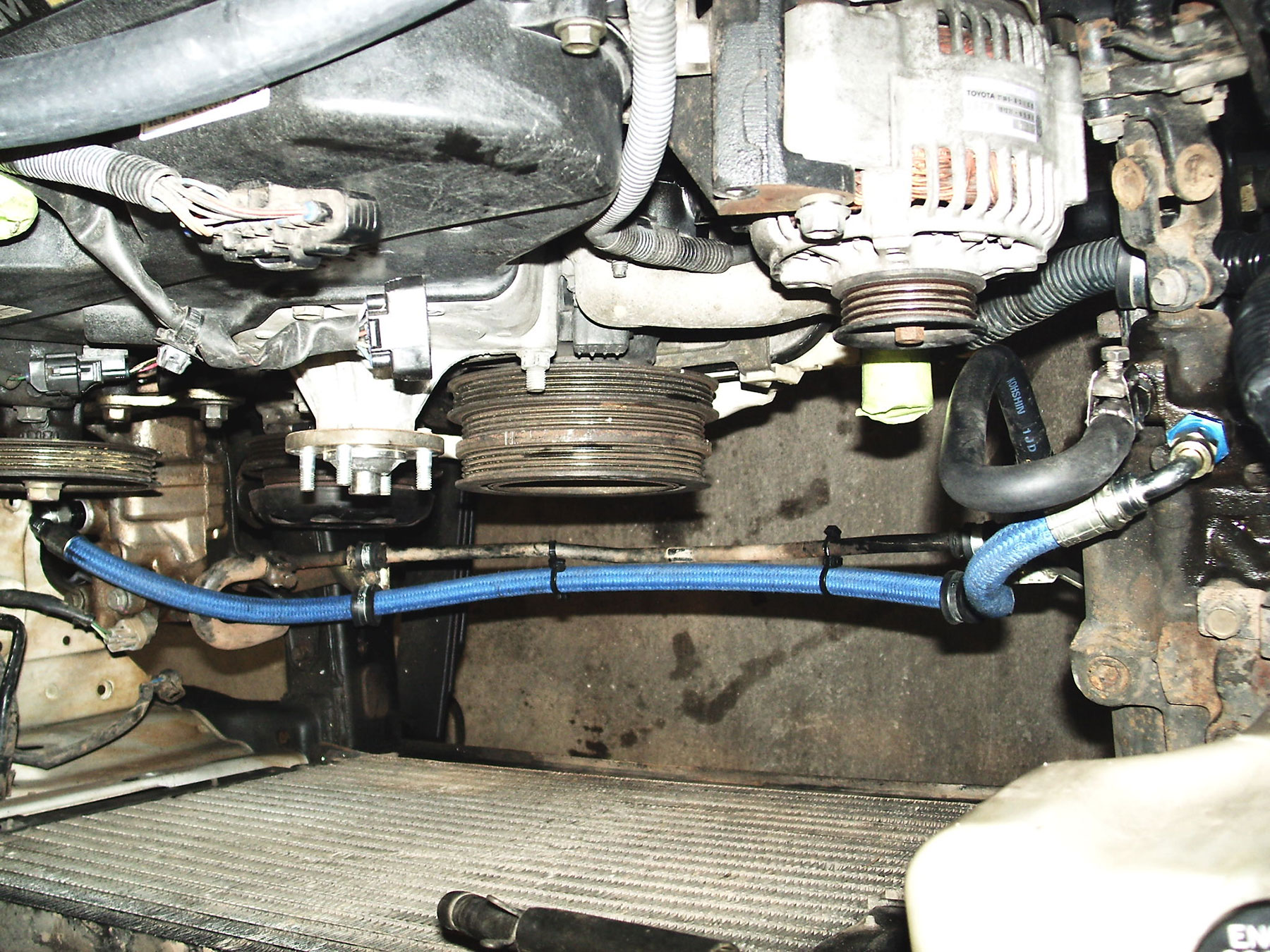
- To replace the power steering return hose, route and install transmission oil cooler hose (3/8”) from the PS pump to the steering gear or ABS actuator. The hard line for return and the related brackets can be re-used. Using the hard line may help secure both the high-pressure and return hoses in place beneath the radiator fan shroud. In this case, simply replace the return hose on either side w/ 3/8: transmission oil cooler hose, or use replacement molded hoses from the recipient application, available through ORS. Install and tighten the hose clamps (#6). See pic #41-41c.
-
- Pic 41 – PS High Pressure Replacement Hose for RW ABS + formed return hoses installed
-
- Pic 41a – PS High Pressure Replacement Hose for RW ABS + formed return hoses installed
-
- Pic 41b – PS High Pressure Replacement Hose for RW ABS + formed return hoses installed
-
- Pic 41c – Molded return hose, cut-to-fit on RH-side ONLY
-
- ABS Models: If the original HP PS hose/line assembly from the ABS actuator to the power steering gear is in poor condition, ORS offers a replacement. If this ORS replacement hose is being used (ORS-EC048), repeat this process to replace the original hose between the ABS actuator and the steering gear. Be sure to use the provided gasket to seal the adapter to the actuator. Route this hose along the original high pressure hose brackets, using the provided closed clamps to fasten the hose, see illustration. See pic 41-41b
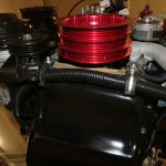
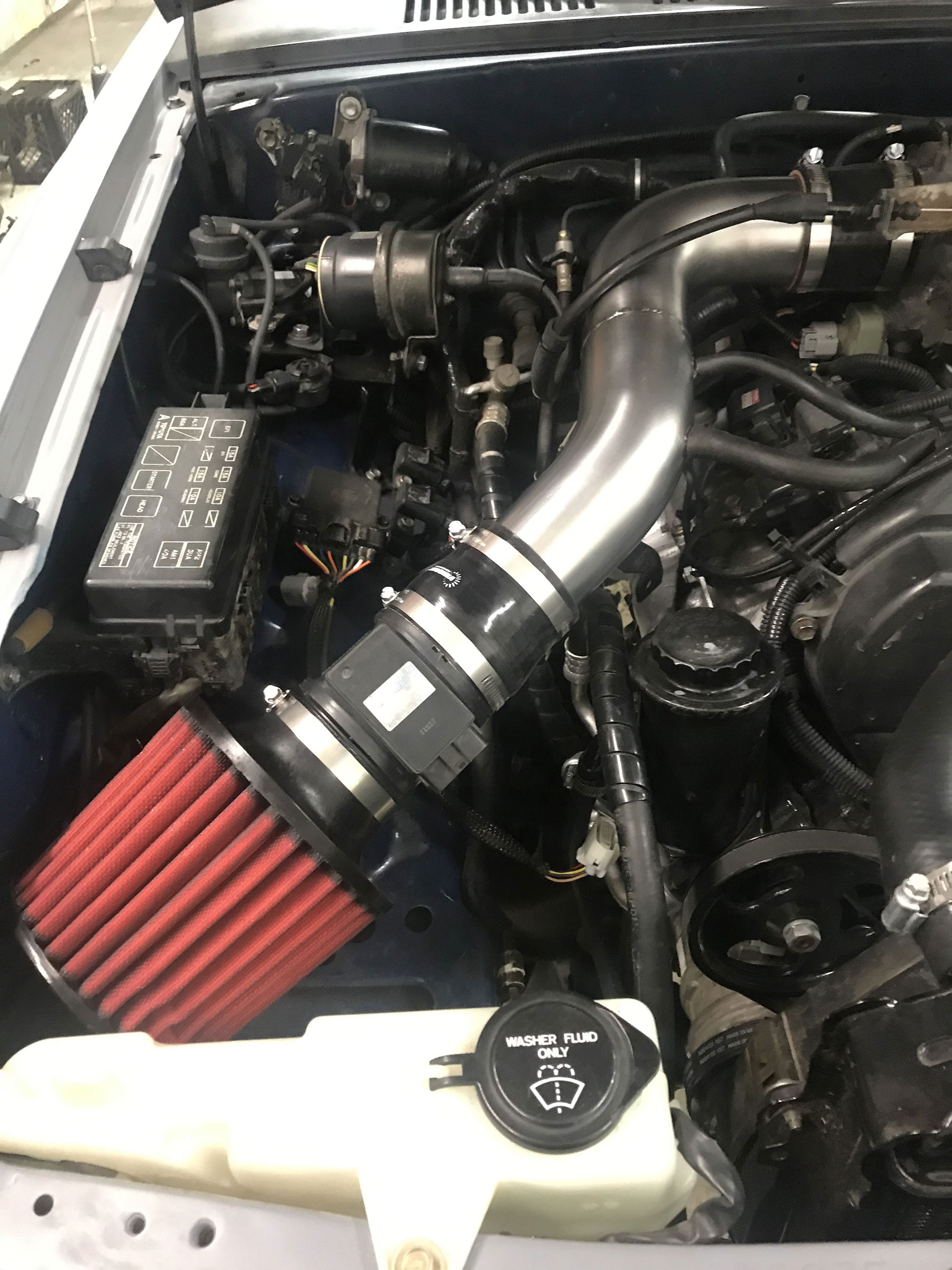
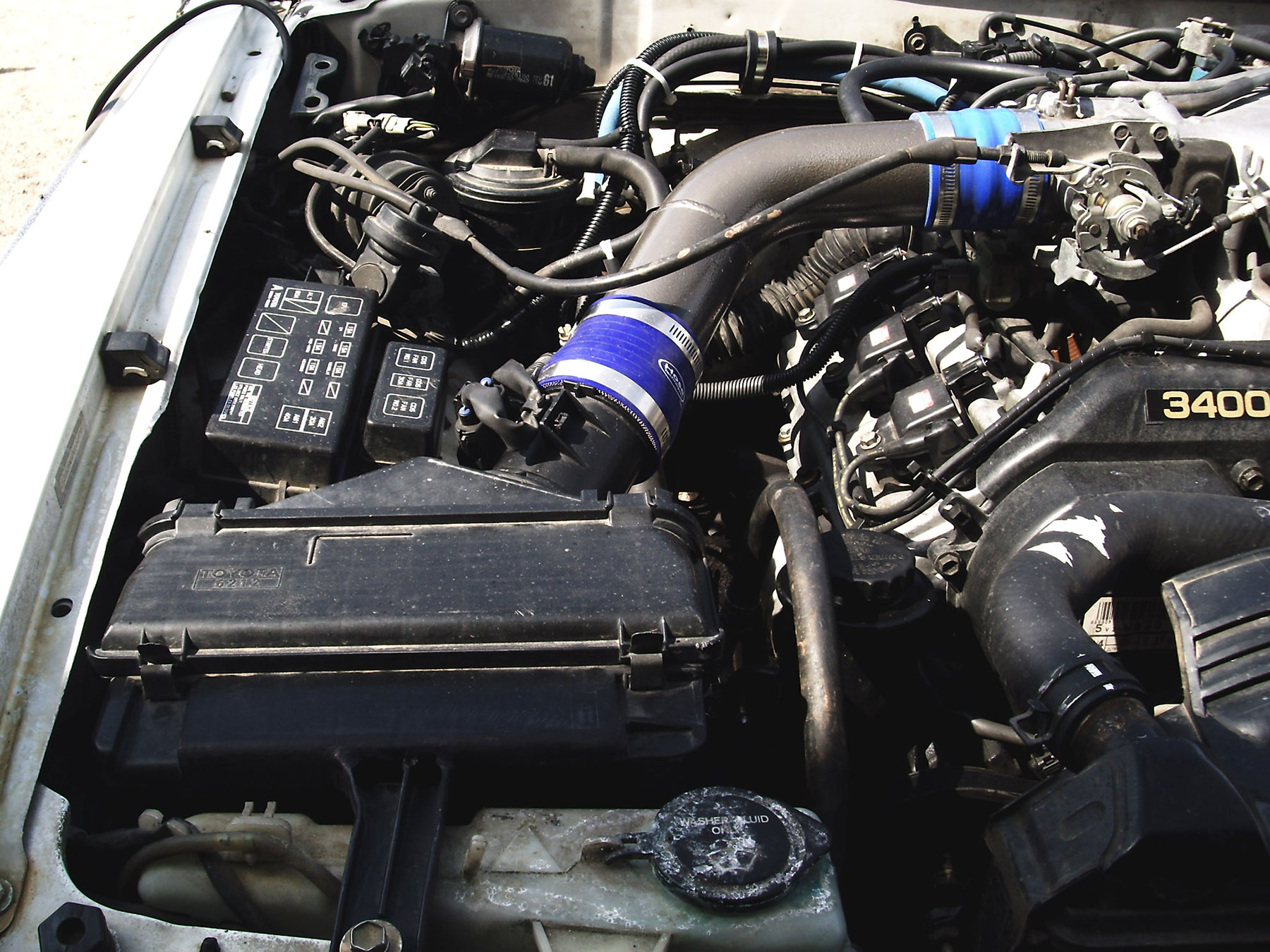
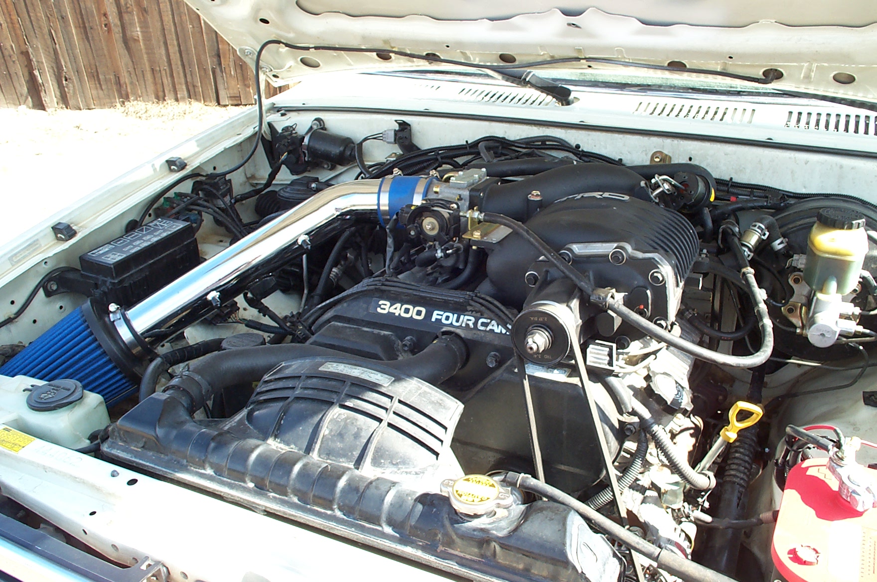
Intake System
Install intake system, this includes intake tubing, MAF and air box/filter:
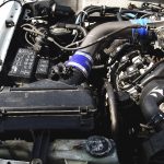
- If using the ORS Intake system, refer to the illustration. See Pic #43
-
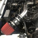
- Pic 43 – ORS Intake Installed
-
- An OEM donor air box can be modified to fit. This normally involves modifying the plastic tabs. Using the OEM air box will also normally require modifying the intake tubing or building a custom intake tube between the throttle body and air box. See pic #44
-
- Pic 44 – OEM Air Box modified to fit
-
- An after-market cold-air system can be used. These may require some trimming to shorten the tube. For this reason we recommend using a cold-air intake w/ tubing constructed of metal, not plastic. See Pic #45
-
- Pic 45 – Aftermarket Cold-Air Intake modified to fit
-
- Another alternative is constructing a custom intake from 2.75” tubing and couplers. The 5VZ uses one of two types of MAF (Mass Air Flow Sensor). Either can be used and work. However, the connection pin-out is different, see the supplement if you are using an MAF from a different application than specified.
Throttle Cable
Two options are recommended for the throttle cable:
- A 3VZ-based throttle cable can be made to work. The throttle bracket on the engine must be modified to fit the cable at the throttle body with proper adjustment.
- A 5VZ donor cable will also work (Tacoma/4Runner). This cable must be modified where it passes through the firewall. The grommet must be turned around to match the orientation of the recipient throttle cable.
The two above options will normally work in a 22R/22R-E recipient vehicle.
2001-2002 4Runner and most 2003-2004 Tacoma/Tundra donor engines will be equipped with an ETCS (Electronic Throttle Control System), “drive-by-wire”. This will have a plastic throttle linkage instead of metal. This is a very simple system that is contained on the throttle body and works well. The conventional throttle cable will connect to this throttle linkage in the same manner. Cruise control for these donor applications was operated by the engine ECU via the ETCS. In a swap, the cruise control also must operate via the engine ECU and ETCS. See the wiring supplement near the end of this guide for electrical connections related to cruise control.
Evaporative and Vacuum Routing (ORS-EC099)
The evaporative emissions system (EVAP) can be made to work with either the 3VZ/22R-E EVAP canister or the 5VZ EVAP canister. The ’95-’96 T100 and ’95 Tacoma used an older, one-valve system with a round canister. The ’96-’00 4Runner, ’96-’01 Tacoma, ’97-98 T100 and ’00-02 Tundra used a rectangular under-hood canister w/ 2 valves and a sensor. The ’02-04 Tacoma, ’01-’02 4Runner and ’03-04 Tundra utilize the same system, but have canister mounted near the fuel tank + an additional valve (CCV). We recommend the use of the donor-type EVAP system; this is the only way to ensure that the EVAP system will operate without trouble codes. However, we recommend the use of the under-hood, rectangular-style canister for donor applications that had the canister mounted near the tank (unless your local emissions testing center will not allow this). Install the EVAP canister using the ORS EVAP bracket (for rectangular-type), or fabricate a bracket. See Pic #46 & 46a
-
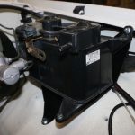
- Pic 46 – ORS EVAP Trays installed, ORS offers two types
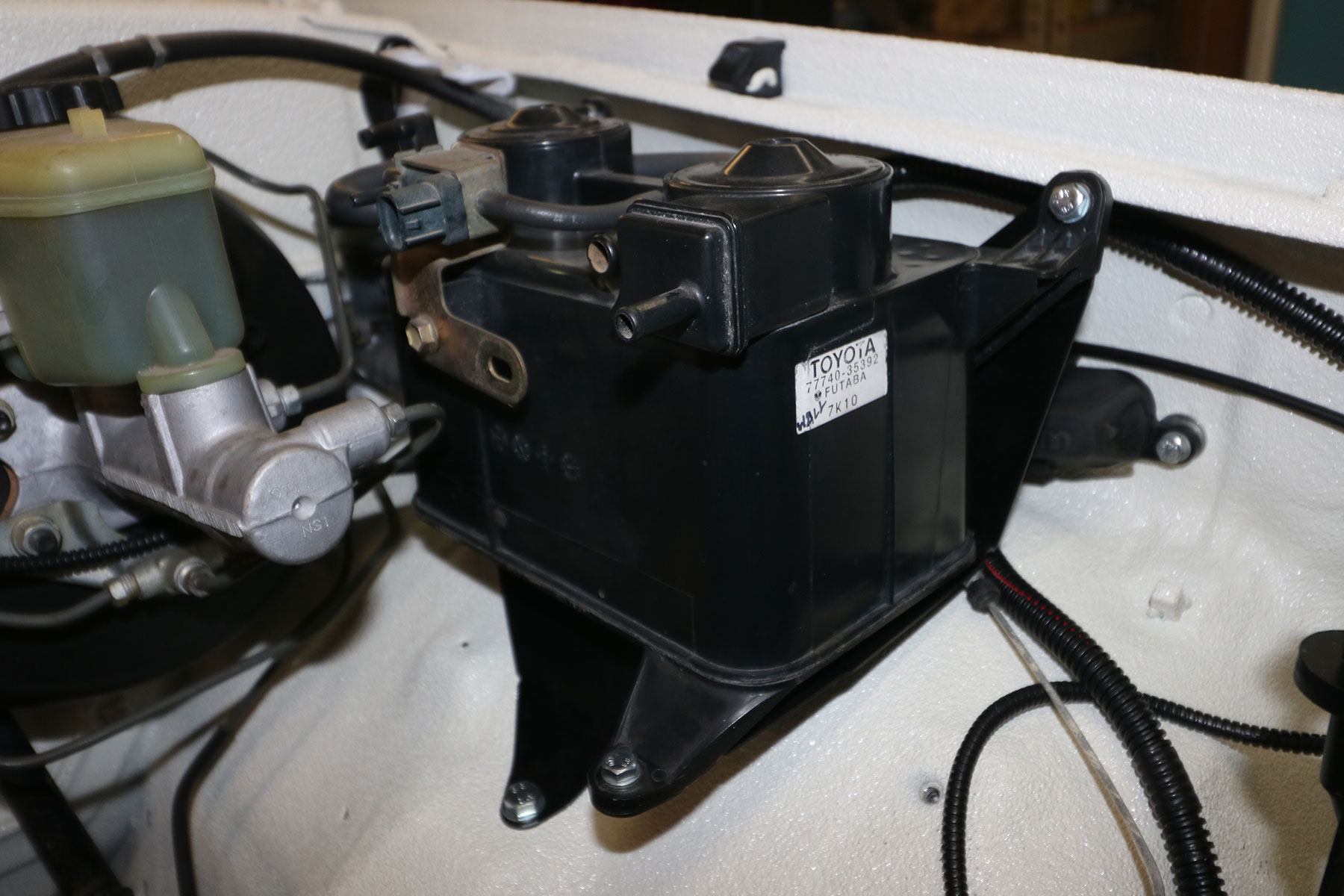
-
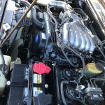
- Pic 46a – ORS EVAP Trays installed, ORS offers two types
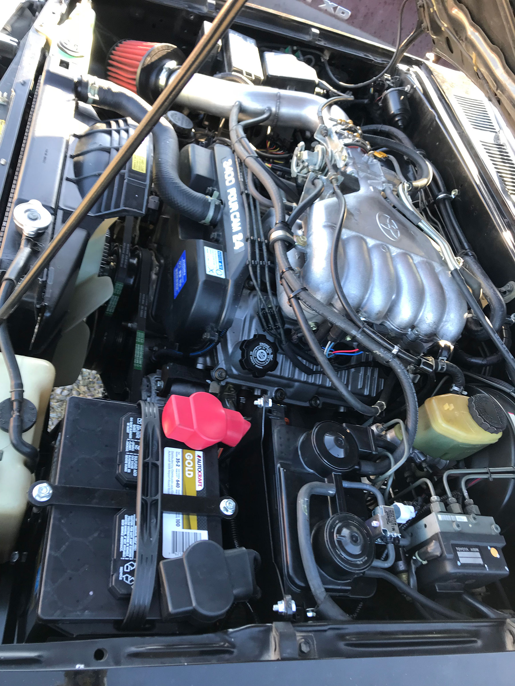
- Mount the EVAP purge VSV and if applicable, the vapor pressure sensor, vapor pressure VSV, and CCV (for latest donor type) in suitable locations. Do not mount the purge VSV directly to the fender/firewall; it will create a buzzing sound. This is best mounted to the EVAP canister or the back of the intake plenum.
- Using the appropriate vacuum illustrations, route/install vacuum hoses for the EVAP system + additional vacuum hoses shown in the illustrations. Refer to Emissions and Vacuum illustrations that match donor application
-
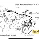
- Emission Layout/Schematics: 96-99 Tacoma, 96-98 4Runner, 97-98 T100, 00 Tacoma/Tundra FED, 99-00 4Runner FED donor
-
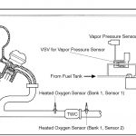
- Emission Layout/Schematics: 96-99 Tacoma, 96-98 4Runner, 97-98 T100, 00 Tacoma/Tundra FED, 99-00 4Runner FED donor
-
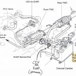
- Emission Layout/Schematics: 01-04 Tacoma/Tundra, 01-02 4Runner, 99-00 4Runner CA, 00 Tacoma/Tundra CA donor
-
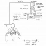
- Emission Layout/Schematics: 01-04 Tacoma/Tundra, 01-02 4Runner, 99-00 4Runner CA, 00 Tacoma/Tundra CA donor
-
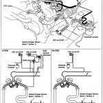
- Emission Layout/Schematics: 95 Tacoma, 95-96 T100 donor
-
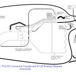
- Vacuum Routing with use of 5VZ Canister
-
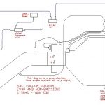
- Vacuum Routing with use of 3VZ Canister
-
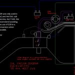
- Vacuum Routing: 95 Tacoma, 95-96 T100 ONLY
-
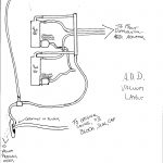
- Automatic – Differential – Disconnect system vacuum routing
-
- Install the brake booster hose between port on LH side of intake plenum and brake booster. Utilize the recipient brake booster one-way valve. Be sure this is turned in the proper direction: air will flow from booster to engine.
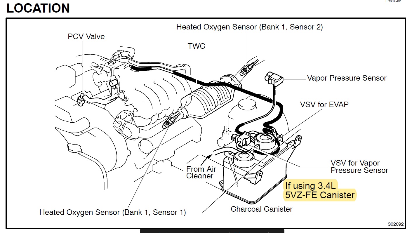
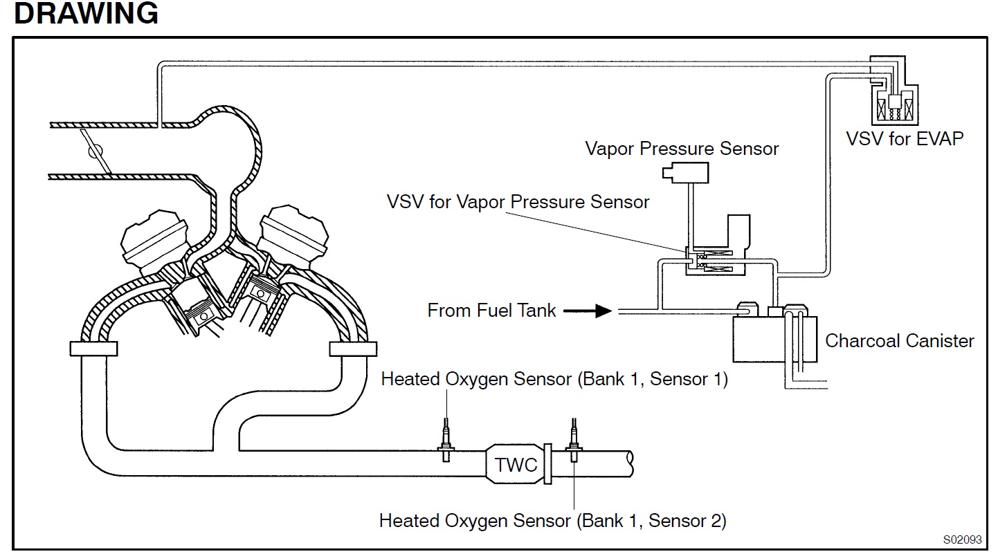
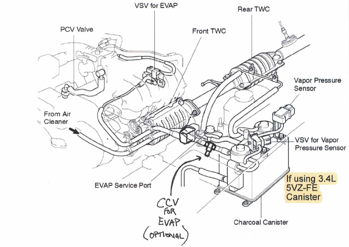
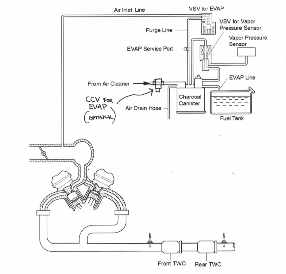
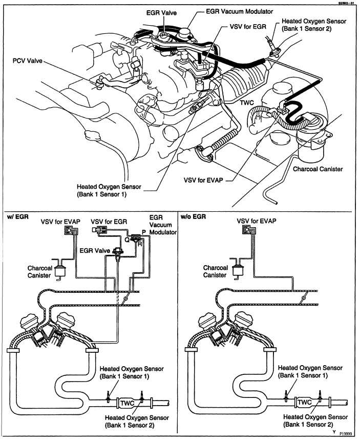
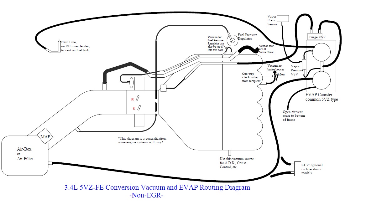
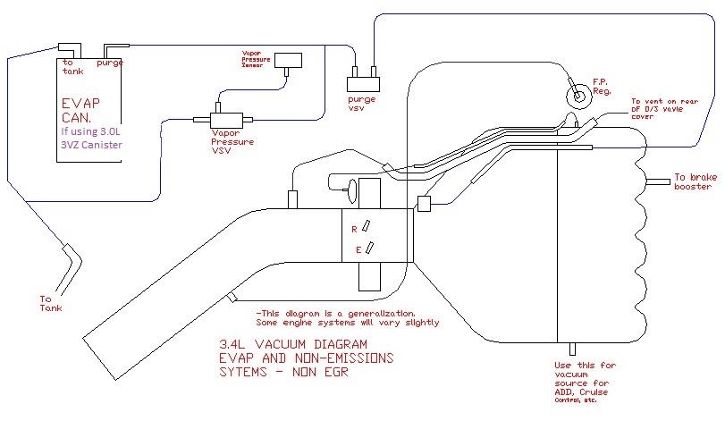
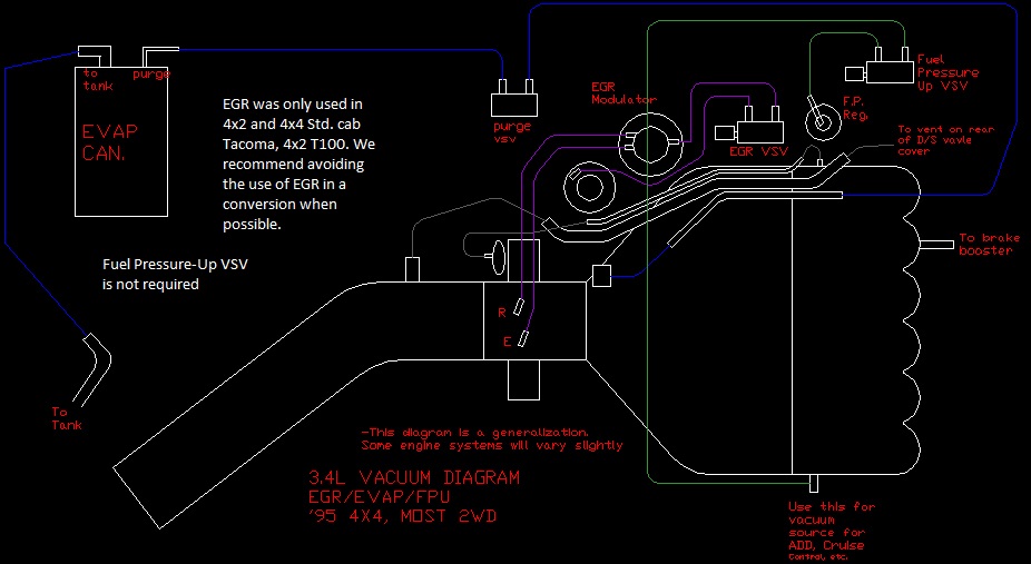
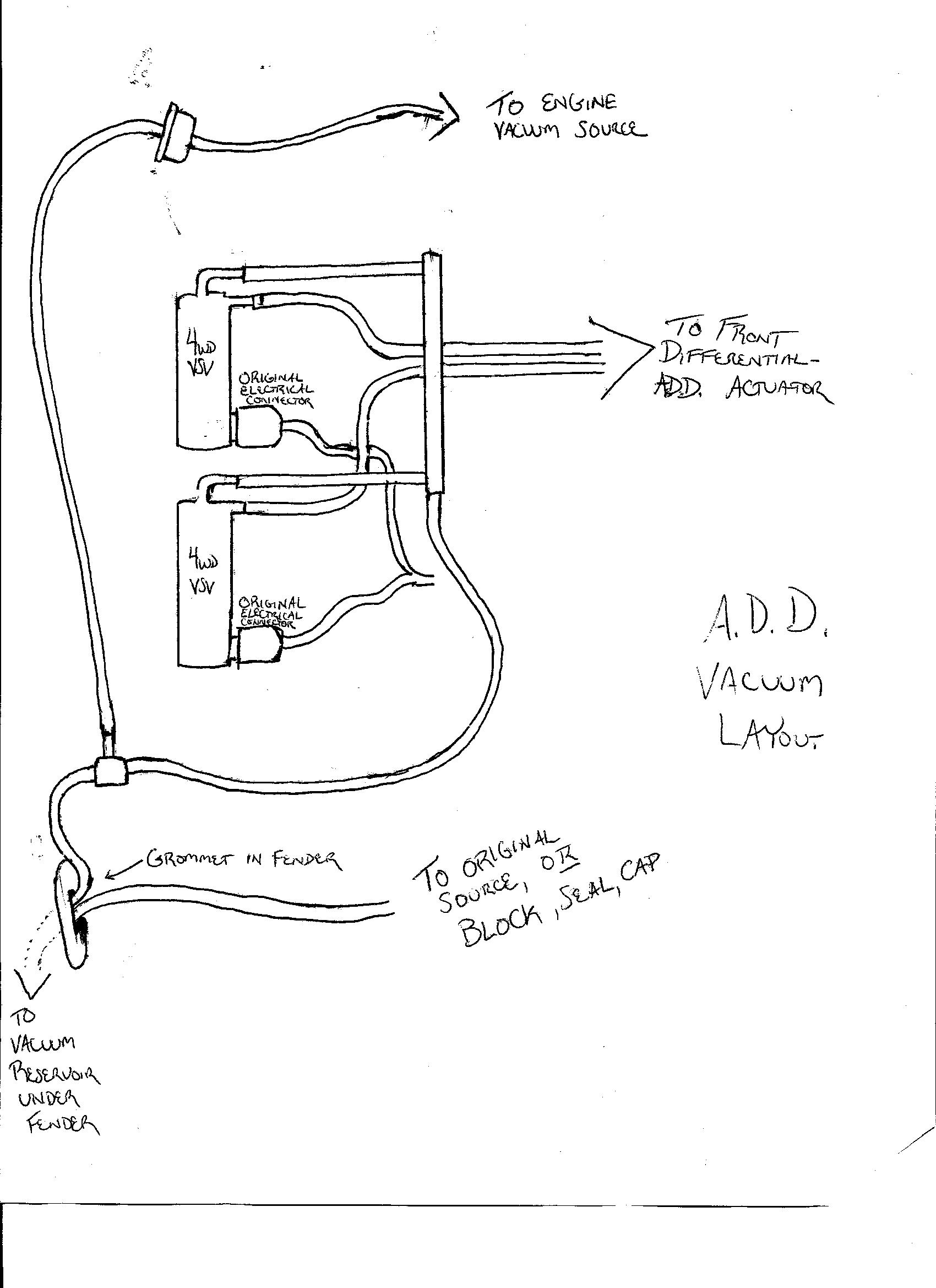
Exhaust System
This is a good time to build the exhaust system but it can also be done at the end of the swap. The 5VZ is regarded as a one-bank system; the two banks of the engine must be joined before the upstream O2 sensor. For this reason we do not recommend a true dual-exhaust. To run efficiently, the upstream O2 sensor must be placed in the collected exhaust stream, for both banks. It is important to match the exhaust system components/design to the donor application (based on ECU). We also recommend the use of 5VZ-based O2 sensors, matching the donor-type. There are two different basic emission setups used with the 5VZ engine:
- ’95-’99 Tacoma, ’00 Tacoma non-CA, ’98-’98 T100, ’96-’98 4Runner, ’99-’00 4Runner non-CA, ’00 Tundra non-CA: this system requires one catalytic converter with one O2 sensor before the converter (upstream, B1S1) and one O2 sensor behind the catalytic converter (down-stream, B1S2). See pic, single-converter exhaust
-
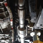
- Exhaust system, single-converter
-
- ’00 Tacoma CA, ’00 Tundra CA, ’01-’02 4Runner, ’01-’04 Tacoma, ’01-04 Tundra: this system used two catalytic converters, in series. The upstream sensor (B1S1) is an Air/Fuel ratio sensor, which looks like an O2 sensor, but operates differently and is placed before the converters. The down-stream (B1S2) sensor is a conventional O2 sensor and is placed after the catalytic converters. See pics, dual-converter exhaust
-
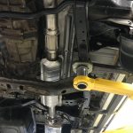
- Exhaust system, dual-converter
-
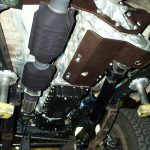
- Exhaust system, dual-converter
-
- We do not recommend the use of an original 3VZ/22R down-pipe and catalytic converter. The exhaust system should be at least 2.25” in diameter from front to back. The older down-pipes/converters are too small. In many cases a custom down-pipe will need to be built. We recommend 2.5” when building new exhaust, if parts from an older system are used, be sure they are at least 2.25” in diameter.
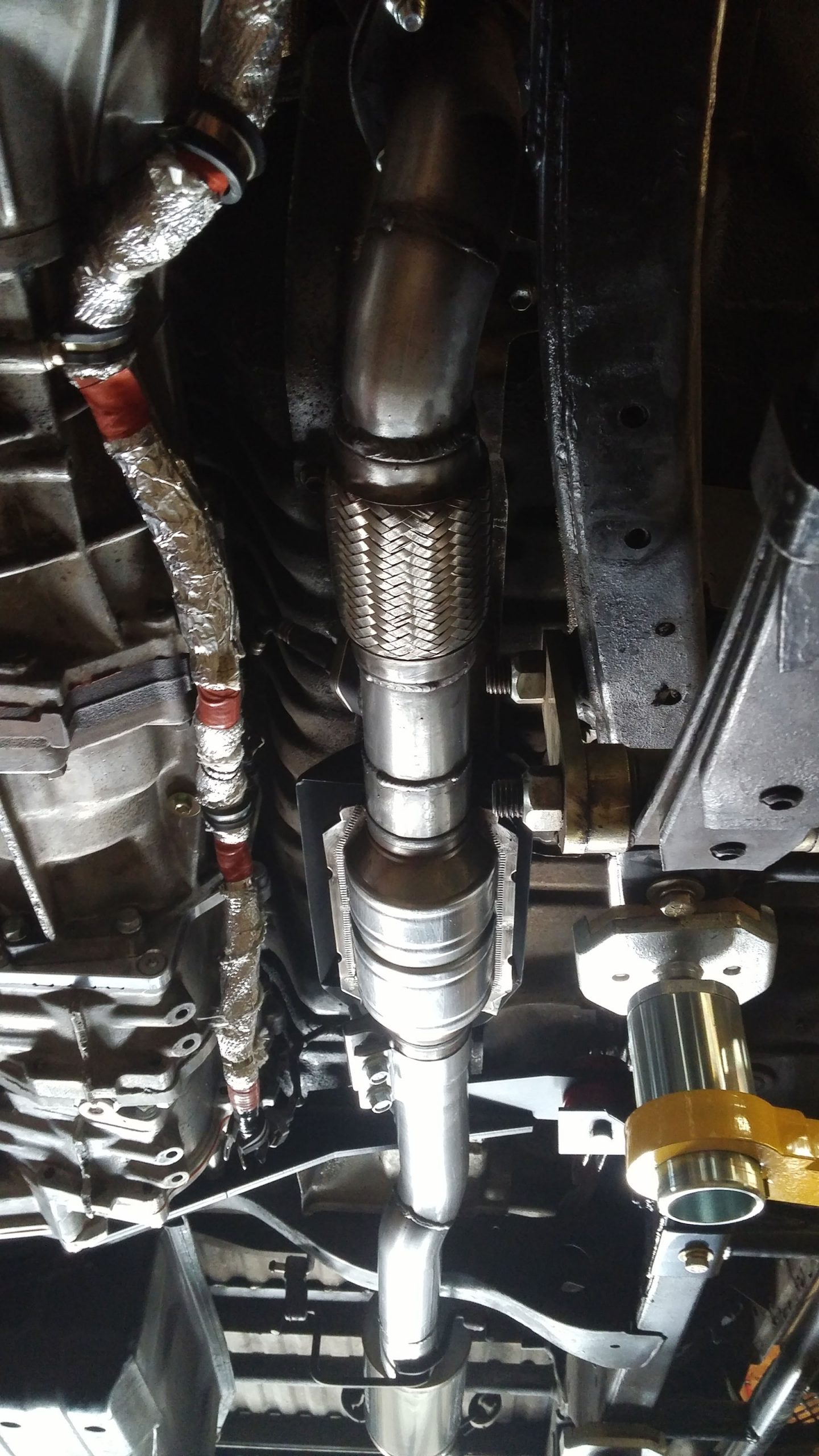
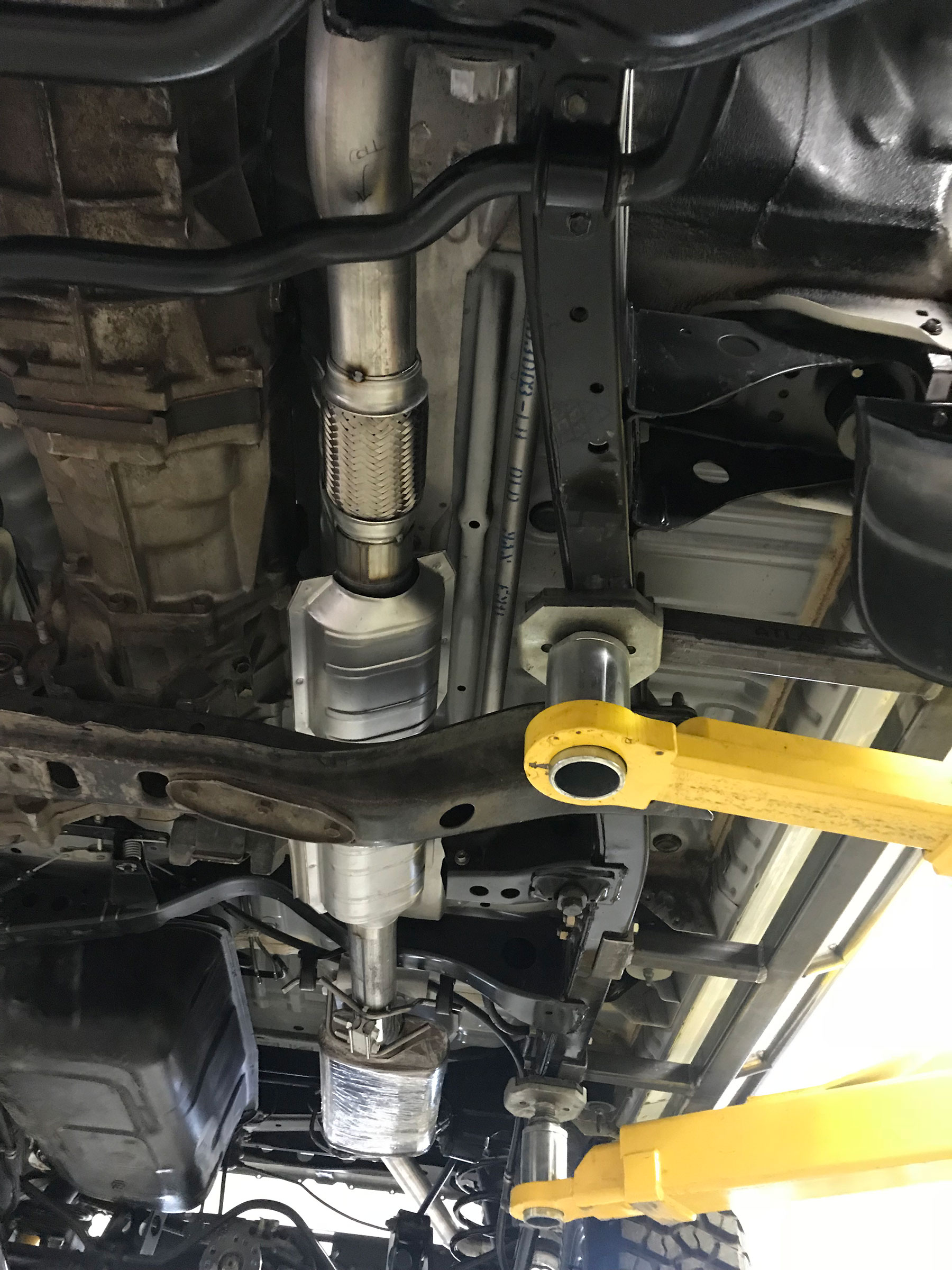
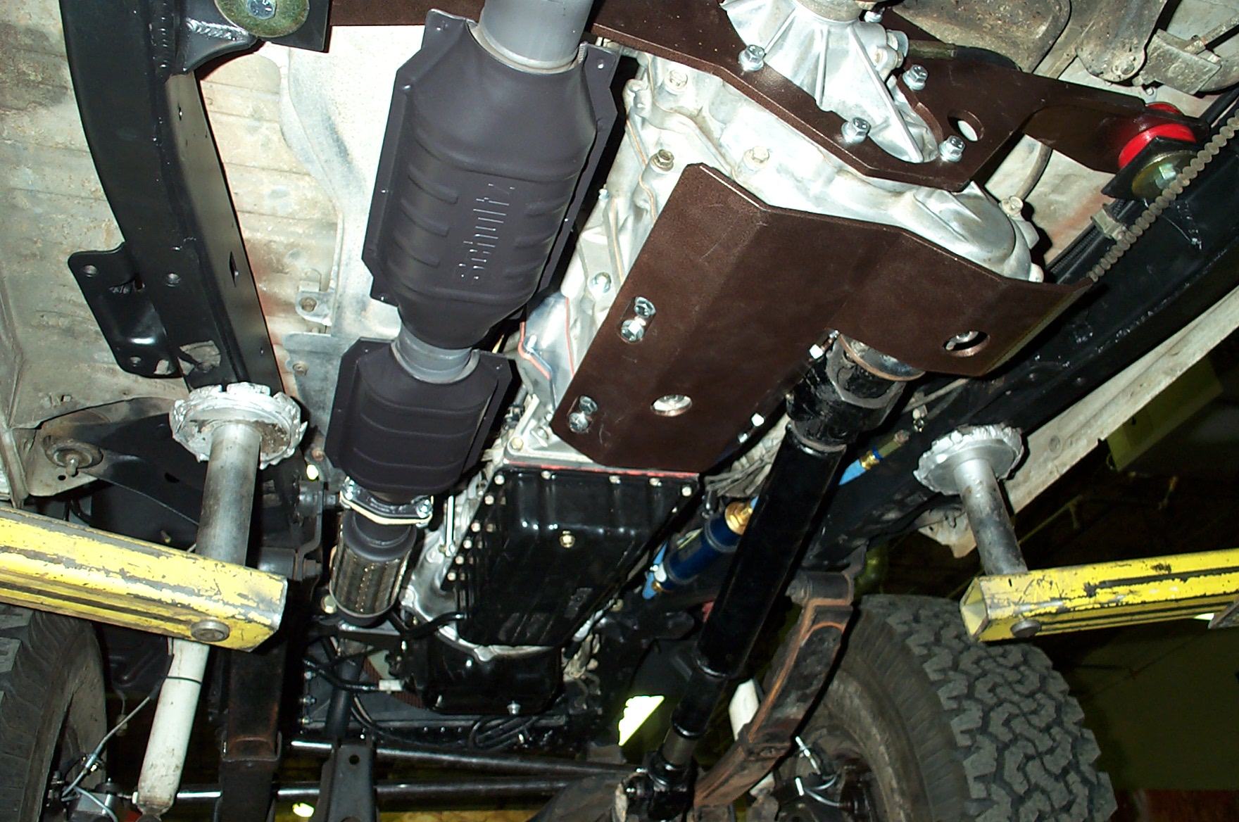
If using the ORS Exhaust Crossover Pipe or ORS 5VZ Performance Header Set, refer to these specific instructions above.
Down-Pipe (ORS-EC078, ORS-EC070AX)
- The ORS 5VZ Header Down-Pipe Extension (ORS-EC078) can be used at this point to route the down-pipe over the OEM sway bar. The loose weld-on flange is a starting point for the rest of the exhaust when not using the down pipe extension. Use the provided collector gasket and install the 10mm x 40mm bolts w/ locknuts through the flanges with the flat washers on the bolt head side at this connection. See pic #47
-
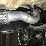
- Pic 47 – Down-pipe for Header system, used to route over 86-95 OEM sway bar
-
- The outlet of the ORS Crossover Pipe will be aimed toward the top of the frame. To achieve necessary clearance, this may require that 2 exhaust bends are used immediately after the collector, the first pointing toward the transmission and the second pointing to the rear of the vehicle. It may be necessary to cut and join these bends together due to space constraints. For select Crossover Pipe applications, ORS also offers a down-pipe for the Crossover Pipe, which will get the exhaust around the frame and pointed to the rear of the vehicle. See pictures #12, 13, 13a
-
- Pic 12 – Down-pipe fabricated to clear frame
-
- Pic 13 – ORS Down-Pipe for Crossover Pipe
-
- Pic 13a – ORS Down-Pipe for Crossover Pipe
-
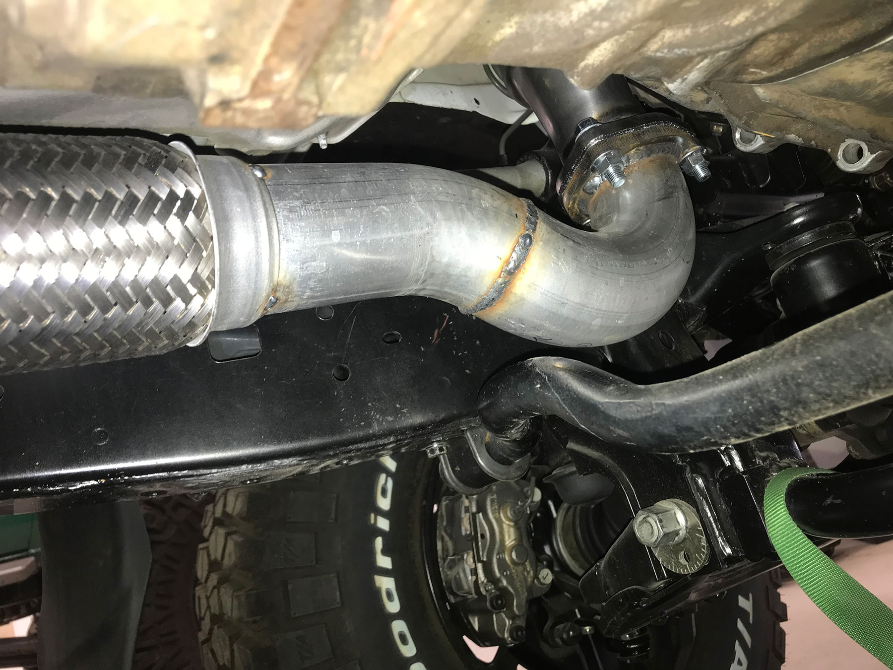
Conversion Wiring Install (ORS-EC020, ECO21, EC022, EC023, EC024, EC025, EC026, EC029)
*****NOTICE TO CUSTOMER: If there is a problem suspected with the wiring harness, contact ORS. DO NOT cut, alter, or dissect the ORS conversion harness. ORS accepts no responsibility for a harness that has been tampered with.
Note: these instructions refer to the Toyota Engine Computer as an ECU. If wire colors or connections described in these instructions do not match your specific application, please call ORS, we will gladly assist.
ORS offers two format-types regarding Conversion Wiring: Adapter and Engine. Adapter refers to the Adapter Harness that also uses original/donor used engine wiring to complete the circuit. Engine refers to all-new wiring that replaces the original/donor engine wiring. Steps pertaining to one type or another will be referenced accordingly.
- ORS recommends the use of the donor battery harness for applications with the battery under the hood, on the LH-side. This is the harness that connects the battery terminals to the starter and engine grounds in the donor vehicle. The starter wiring also contained in this harness. If this harness is damaged or not available, ORS offers a conversion replacement for this harness, PN ORS-EC046. The ORS version of the battery harness is also help with body-lifted applications. Install this harness to the engine using the original configuration. Connect the engine ground cable and the starter terminal and cable. Install battery harness on engine. Do not connect the battery terminals at this time. If using the ORS Battery harness, refer to the provided ORS Battery Harness Installation Notes.
- Adapter: Refer to the Adapter Harness install illustrations and sketch of Adapter harness in RH kick-panel.
-
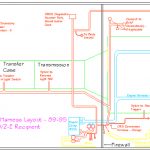
- Adapter Wire Harness Install Illustrations
-
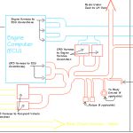
- Adapter Wire Harness Install Illustrations
-
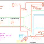
- Adapter Wire Harness Install Illustrations
-
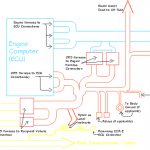
- Adapter Wire Harness Install Illustrations
-
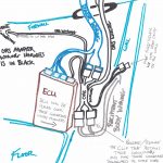
- Sketch of Adapter harness in RH kick panel area
-
- Adapter: Be sure the 5VZ original/donor engine wiring harness is properly installed on the engine and all connectors are plugged in. Route the engine harness lead behind the alternator and down the LH side of the engine and transmission. We highly recommend wrapping the harness with heat tape or exhaust wrap anywhere the harness passes close to the exhaust.
- Adapter: Connect the original/donor engine harness to the oxygen sensor leads. Depending on your application, there may only be one oxygen sensor connector in the engine harness. If only one is found, the other is contained in the ORS harness and will be connected later.
- Adapter: Be sure the wiring harness is secured clear of exhaust parts to prevent heat damage. See pic 48b.
-
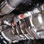
- Pic 48b – For Adapter Harness: donor engine wiring shielded and routed near exhaust
-
- Adapter: Route the original/donor engine harness main loom (under hood) toward the RH side. We recommend routing this harness in front of the fuel and brake lines, under the clutch hose and behind the original evaporative canister. The canister firewall mount is a good location to secure this main loom to the firewall using routing clamps. See pic 48a
-
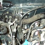
- Pic 48a – Engine wiring routed into firewall
-
- Adapter: Route the original/donor engine wiring harness through the RH side firewall and down to the kick-panel. Connect the ECU connectors to the ECU and lay the ECU in the kick panel area.
- Adapter: Lay the ORS Adapter harness near the RH kick panel area. Orient the harness so that the leads are pointing in the proper direction. Connect the Adapter harness ECU connector(s) to the ECU. Connect the Adapter harness to the original engine wiring harness (1-3 connectors). Fold/secure the latch on the top of the connector(s), if applicable.
- Engine: In most cases, it will be necessary to remove the intake plenum from the engine. Place the ORS Engine Harness on the engine, starting w/ the large part of the harness along the topside of the back of the engine. Following the same basic routing of the original engine wire harness, install the ORS Engine Harness on the engine. Make all possible connections. Insulated closed clamps are provided in certain spots on the wiring. Using the pictures and locations as a guide, secure the ORS Engine Wiring to the engine with the provided closed clamps. Be sure harness is secured from contact with hot components. Note: the ECT (coolant temp) sensor near the front of the intake manifold will no longer use the OEM pigtail for connection. See pics 49-55a.
-
- Pic 49 – Engine Wiring Install – Be sure to clamp wiring where indicated
-
- Pic 50 – Engine Wiring Install – Be sure to clamp wiring where indicated
-
- Pic 51 – Engine Wiring Install – Be sure to clamp wiring where indicated
-
- Pic 52 – Engine Wiring Install – Be sure to clamp wiring where indicated
-
- Pic 53 – Engine Wiring Install – Be sure to clamp wiring where indicated
-
- Pic 53a – Engine Wiring Install – Be sure to clamp wiring where indicated
-
- Pic 54 – Engine Wiring Install – Be sure to clamp wiring where indicated
-
- Pic 55 – Engine Wiring Install – Be sure to clamp wiring where indicated
-
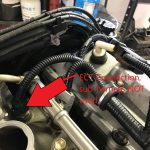
- Pic 55a – Engine Wiring Install – Be sure to clamp wiring where indicated
-
- Engine: Route the transmission/O2 sensor section down the RH fender and under the RH side of the vehicle, along the transmission (follow brake and fuel lines). We highly recommend wrapping the harness with heat tape or exhaust wrap anywhere the harness passes close to the exhaust.
- Engine: Route the section of harness containing EVAP and battery connections to the LH fender-well area.
- Engine: Route the “interior” section of ORS Engine Harness through the RH firewall hole into the interior. This is the section of the harness that has the ECU and body connections. See pic 48
- Engine: Connect the ORS Engine Harness ECU connectors to the ECU. Secure the ‘body ground’ terminal near this section to a suitable body ground.
- In the interior, route the diagnostic lead under the dashboard to the LH side of the vehicle. Find a suitable location under the LH dashboard area and mount the diagnostic (OBDII) connector. This connector serves as the port for an OBDII diagnostic scanner.
- If there is a lead labeled “body ground” near RH kick-panel or the diagnostic connector, connect to a suitable body ground location.
- Securely mount any provided relays/relay boxes.
- Adapter: Disconnect the fuse holder from the ORS harness. Route the harness end of the ‘battery positive’ lead through the firewall on the LH side. Under the hood, re-connect the fuse-holder. Route and connect this lead to the battery positive terminal. Don’t connect the battery at this time.
- Adapter: Route all other leads out the firewall into the engine bay (RH side).
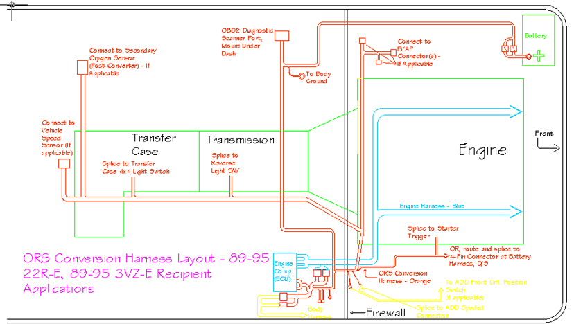
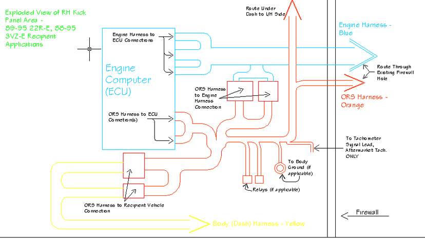
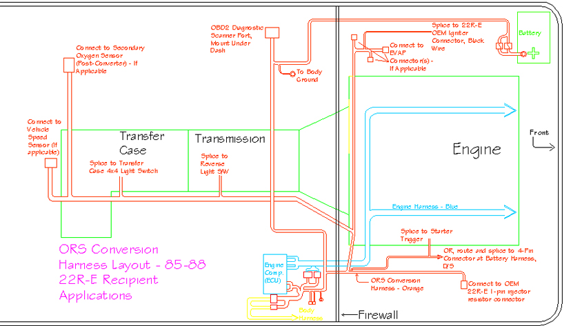
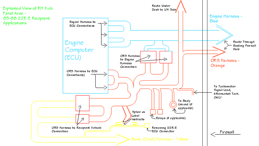
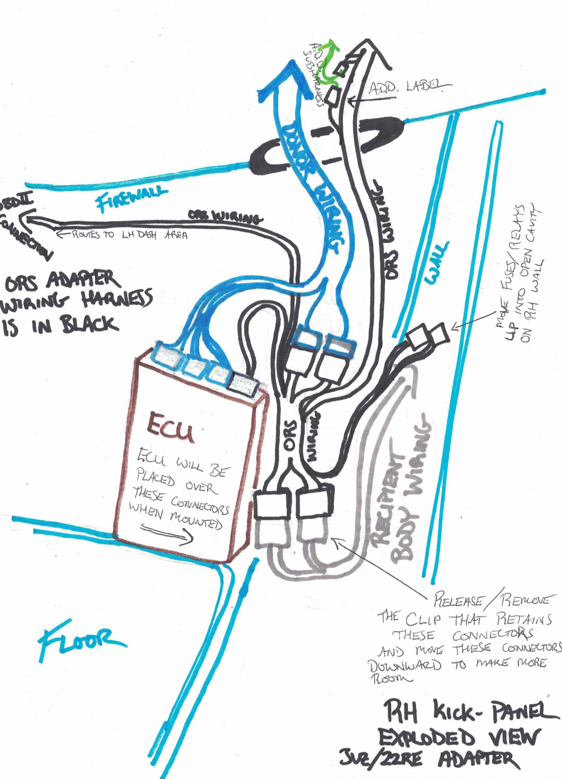
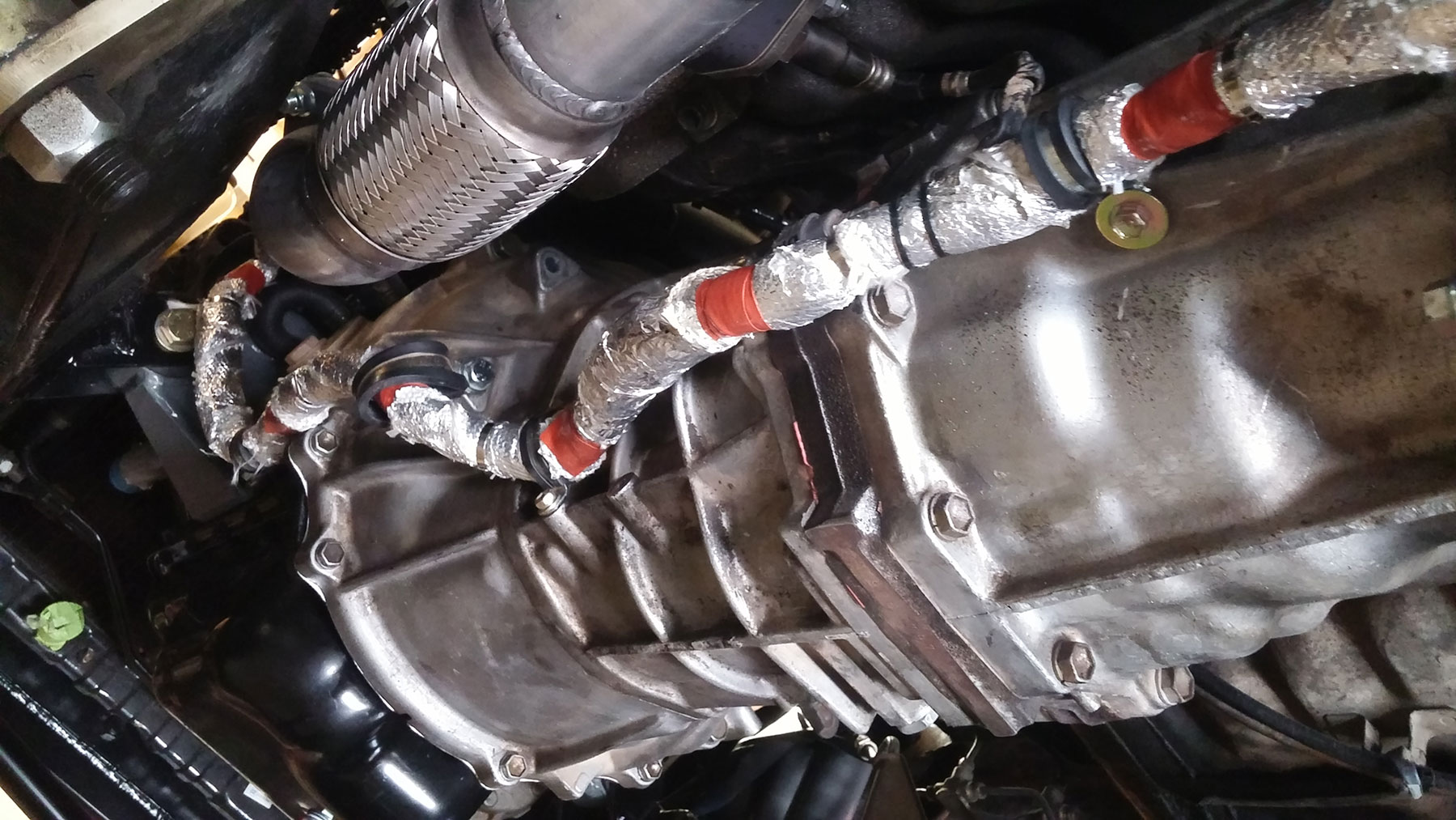
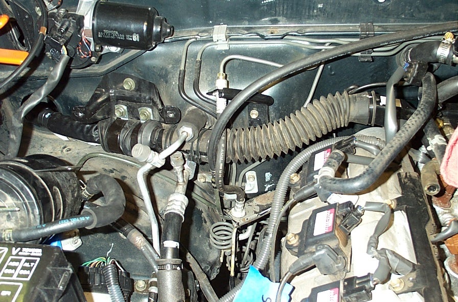
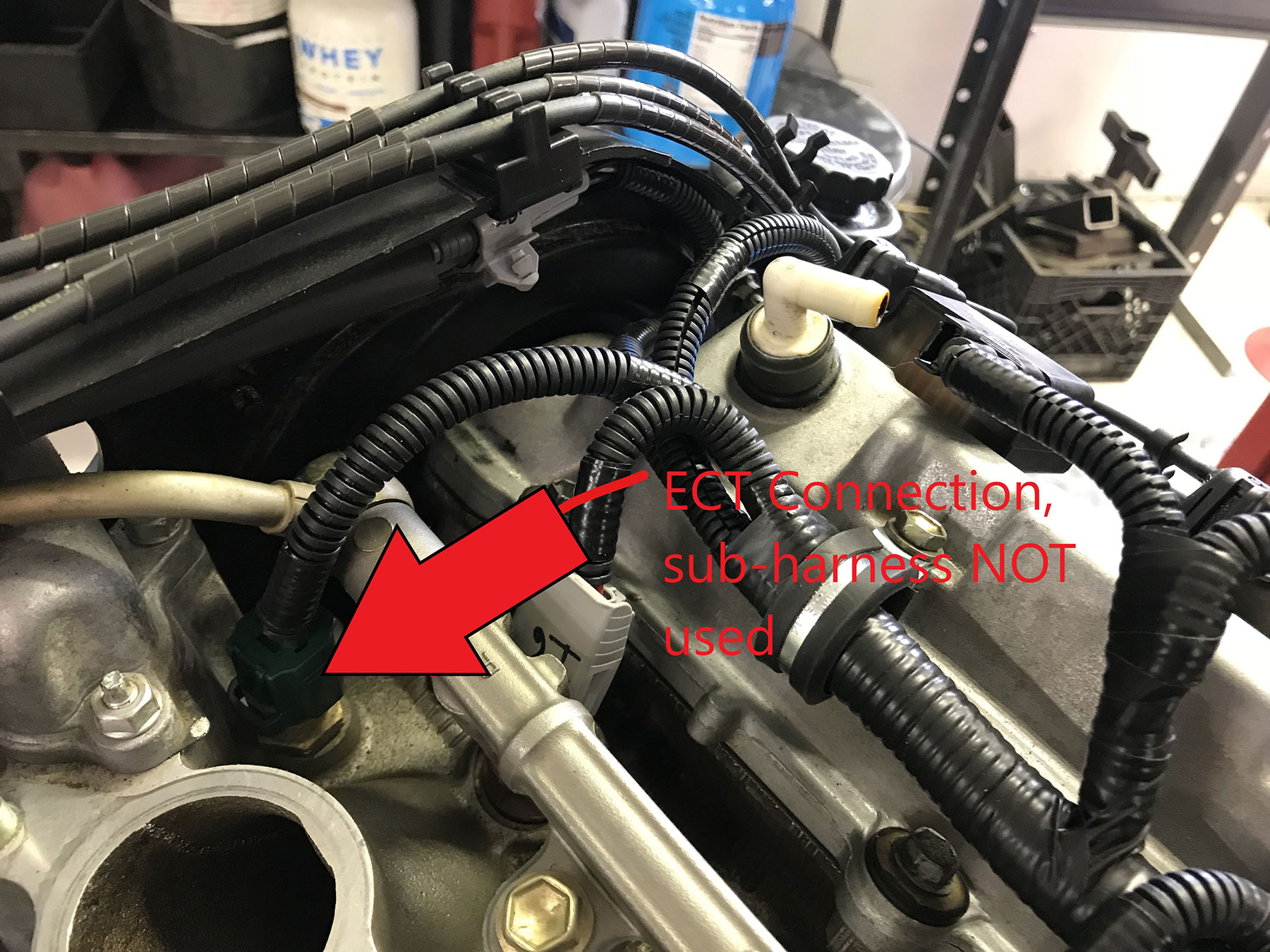
The following 5 steps pertain to 22R-E/3VZ-E recipient vehicles:
- Connect the ORS harness to the vehicle body wiring harness. These are the white and gray or yellow connectors found in the RH side kick-panel (where original engine harness was removed).
- If applicable, for harnesses with leads labeled “to ECU CONN V”: locate the original ECU connector (yellow) still in the vehicle. Cut the appropriate colored wires from this connector and directly splice to the appropriate labeled wires in the ORS harness. Use the wire end that leads into the vehicle’s harness.
- If applicable on A/T models: Route the leads labeled “to ECT or A/T ECU connector” to the connector from the original A/T ECU (computer). Splice the leads to the appropriate wires in the A/T ECU connector as labeled, connecting to the wire end that leads into vehicle harness. The original A/T or ECT ECU is not needed and can be discarded.
- If applicable, connect the lead labeled “injector resistor” to the original injector resistor connector on the RH side fender-well. Connect this lead to the original 1-wire connector. Route the lead labeled “to igniter black wire” to the original 22R-E coil/igniter connector (2-wire green on LH fenderwell), and splice/connect to the solid black wire.
- If applicable: The ORS harness contains a lead labeled “tachometer”. If an aftermarket tachometer is used, this lead will provide the necessary RPM signal. If an aftermarket tachometer is not used, cover the end with tape or shrink-wrap and tape this lead to the side of the ORS harness. Note: If using the original tachometer, it is already pre-wired in the ORS harness.
The following 8 steps pertain to ‘Stand-Alone/Universal’ recipient vehicles:
- Route the harness lead containing the check engine light, diagnostic port, gauge leads, start and ignition leads, and brake switch lead toward the LH side of the vehicle, inside the interior.
- Mount the check engine light in an appropriate location in the LH interior area.
- Connect the “ignition on” signal to an ignition power source. This will be a source that only provides 12V when the key/switch is in the ‘ON’ and ‘START’ positions. The ignition switch is a good place to make this splice connection.
- Connect the “start signal” lead to a start power signal source. This will be a source that only provides 12V when the key/switch is held in the start position, often found at the ignition switch. M/T applications: If the ORS harness does not have clutch safety switch wires, and the use of the vehicle’s clutch safety circuit (if equipped) is desired, use the start trigger wire coming from the original start relay instead of the start wire at the ignition switch.
- Splice the wire labeled ‘brake light switch signal’ into the switching side of the brake light circuit. This will be the side of the switch that only provides 12V with the brake pedal depressed. This is often a green/white wire. The brake signal is not required but recommended.
- With 1-wire speed sensor lead: This one-wire lead is provided when the OEM speedometer and cable is in use. Connect the “to speed sensor signal” wire to the OEM speed sensor signal. This is often a green/blue wire at the instrument cluster. If deriving this signal from an aftermarket source, this will be a 4-pulse-per-revolution square-wave signal (4k PPM).
- With 3-wire speed sensor connector: Connect the ORS 3-wire speed sensor connector to the back of the transmission/transfer case. If using a trans/transfer case w/ a speedometer cable sender, use an electrical-speed-sensor adapter such as the one found through Marlin Crawler to adapt for plug-in. If the trans/transfer case had neither a cable nor electrical speed connection, remove the corresponding hole-plug and install an electrical sender from a similar model. If the ORS harness also contains a wire labeled “speed signal/sender for speedometer” this can provide a speed sensor signal to an after-market speedometer.
- The wires labeled “tachometer”, “water temp”, and “oil pressure” are senders/signals for the corresponding gauges. Connect these leads to their proper gauge sender/signal wire, normally labeled for recipient wire color.
- The Toyota OEM tachometer will require soldering a 10k ohm ¼ watt resistor into the back of the tachometer circuit board. See tach mod pics. These illustrations are images of the rear of the OEM tachometer circuit board. This is accessed by removing the instrument cluster, splitting the case in two via the center clips, then removing the tachometer individually. If this step is not performed, it will not damage anything, but the tachometer will not move at all. Note: the black surface on the gauges is very sensitive to oil from human hands, we recommend wearing clean gloves.
-

- Tach Mod
-
- Tach Mod
-
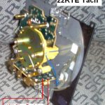
- Tach Mod – 22RTE
-
- Tach Mod
-
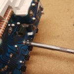
- Tach Mod
-
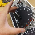
- Tach Mod
-
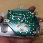
- Tach Mod
-
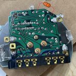
- Tach Mod – T100 3VZ AT
-
- Engine: If a 7th Injector Add-on circuit was provided: the connection labeled “7th injector kit” is available for the use of a 7th Injector Fuel Upgrade Kit, used to enhance a supercharger system. This connection is used for an easy interface to the 7th Injector sub-harness. To install, splice the 7th Injector sub-harness to the provided ORS pigtail, using the wire labels, then connect this connector to the ORS Engine Harness. If a 7th Injector kit is not currently used, leave the 7th Injector connection cap (with small wire loops) in place and store the connector pigtail for future use.
- Adapter: The wire end labeled “7th Injector +B” is intended for the use of a 7th Injector Fuel Upgrade kit, used to enhance a supercharger system. When wiring the 7th Injector sub-harness, a “+B”, ignition on, signal is required from the ‘body wiring’ in the instructions. This will actually come from the Adapter wiring in a swap. The “7th Injector +B” wire end/connection is an easy way to connect the 7th Injector sub-harness to the Adapter wiring for this signal. If not using the 7th Injector kit, this can be left capped and un-used.
- Adapter: Route the transfer case (and sometimes reverse light, oxygen sensor, speed sensor) leads in the ORS harness (under the hood now) down the RH side of the vehicle. Secure the harness to the firewall/lines/hoses a safe distance from the exhaust.
- M/T models: Connect the reverse light connection to the transmission. If the ORS splicing to the reverse light switch is necessary, cut and splice these wires into the reverse light switch on the side of the transmission. This switch is non-directional, meaning each wire has no specific match.
- Adapter: If these leads are not on the Adapter harness, and the donor vehicle’s transmission is being used, connect the reverse light connector from the original/donor engine harness to the reverse light switch.
- Engine: AT models using donor transmission: Connect the ORS harness to the transmission P/N switch, solenoid, speed sensor and temp sensor.
- 3VZ 4×2 A/T models: The 4×2 automatic-transmission may not have a transmission temp sensor installed from the factory. To satisfy the ECU an A/T temperature sensor will need to be installed in the transmission. We suggest obtaining a temp sensor from a donor or a 4×4 3VZ A/T application, or the donor application. There may be a plug/provision for this sensor near or on the transmission cooler lines on the RH side of the transmission. If no plug/provision exists, we suggest using Toyota PNs 90407-14024 & 89429-34010 (with an ORing) to install a sensor in the cooler line. That sensor will then plug into our new harness or donor engine wiring.
- Engine: AT models using A340H recipient transmission: Working on RH side of bell-housing: Connect the ORS harness to the transmission P/N switch and temp sensor. In some cases, the 3.0L neutral safety switch will connect to the 3.4L engine harness. Note: If the P/N switch connector is different, install a neutral safety switch from the donor (3.4L 5VZ) vehicle. In this case, this switch will bolt to the older transmission. Next, connect the white and black transmission connections to the original A340H trans sub-wire harness. Note: Some 1988-1989 A340H Transmissions may have a different A/T Temp Sensor Connection. In this case, obtain and install an A/T Temp Sensor from a 1990 and newer model for connection to the ORS Wiring Harness.
- If applicable: Cut and splice the leads labeled “4WD indicator switch” into the transfer case position switch. This switch is also non-directional. Be sure that all connections are secure and sealed. Also be sure the wiring harness is safely routed under the vehicle. If the 4WD indicator switch only has one wire, use the ORS light green wire, brown will not be needed.
- If applicable, connect the “speed sensor” connector to the vehicle speed sensor on the rear of the transfer case/transmission.
- Engine: Connect the ORS harness to the Oxygen Sensors (or A/F Ratio Sensor). The connection closer to the engine is for the upstream sensor, while the sensor further from the engine is for the downstream sensor. The upstream sensor will likely be routed over the transmission case, while the downstream sensor can be routed over the transmission or around the rear of the transmission. Be sure to secure the wiring and apply heat shield tape/material anywhere the wiring passes close to heat.
- If applicable, route the “fuel pump” lead to the fuel pump. If the ORS harness has one wire for fuel pump, splice to the positive fuel pump wire, leading into the pump. This is usually a blue wire. The blue wire going back into the body wiring should be sealed/capped, it will not be used. If the ORS harness has two wires for fuel pump, this will make an all-new connection to the pump; connect according to the labels.
- Be sure the wiring harness is secured and clear of exhaust parts to prevent heat damage.
- Connect to the appropriate evaporative (EVAP) valves and vapor pressure sensor (EVAP). Use the provided EVAP hose diagram to identify the proper parts. With Adapter wiring, some EVAP connections may be in the original/donor engine wiring while other connections may be part of the Adapter wiring.
- The lead labeled “starter” (under the hood) is ultimately connected to the smaller “trigger” terminal on the starter. This can be done one of two ways. 1) If using the 5VZ battery harness: route the “starter” lead across the engine bay (in front of radiator), to the battery area. Cut the 4-pin (1-pin on T100 engines) connector from this harness (located near the battery terminals). Splice the wire labeled “starter” to the black wire in this connector. Be sure the connection is secure and sealed. 2) If not using the 5VZ battery harness, route the “starter” lead to the starter. Directly connect this lead to the trigger terminal on the starter.
- Mount the 5VZ ECU. The brackets bolted to the side of the ECU share the same bolt pattern as all Toyota ECU’s. This allows the installer to share brackets from any ECU to help in the mounting process. Find a location near the passenger side kick-panel that will house the ECU. Be sure that the ORS wiring harness and the engine wiring harness leads will reach the ECU and plug in. If the vehicle does not have A/C it is possible to mount the ECU behind the glove box.
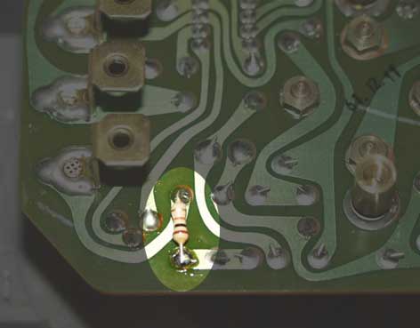
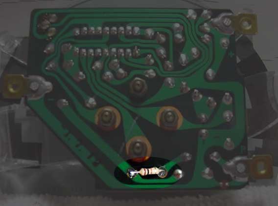
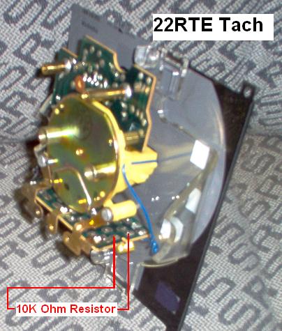

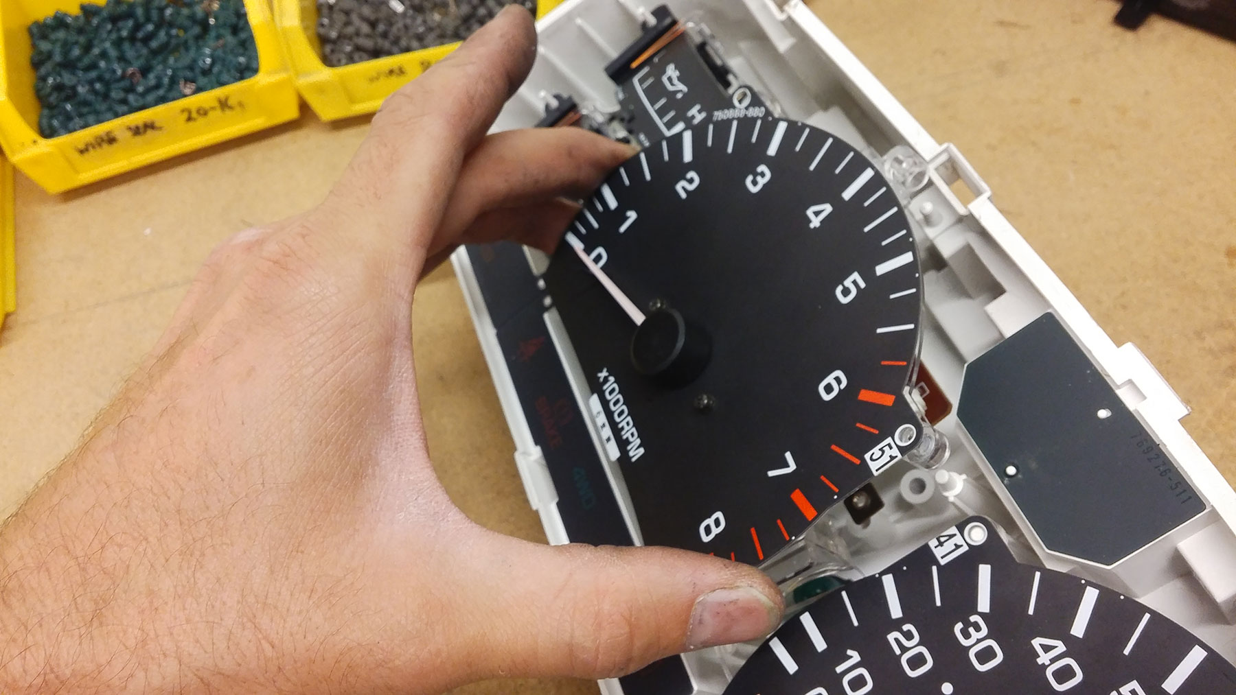
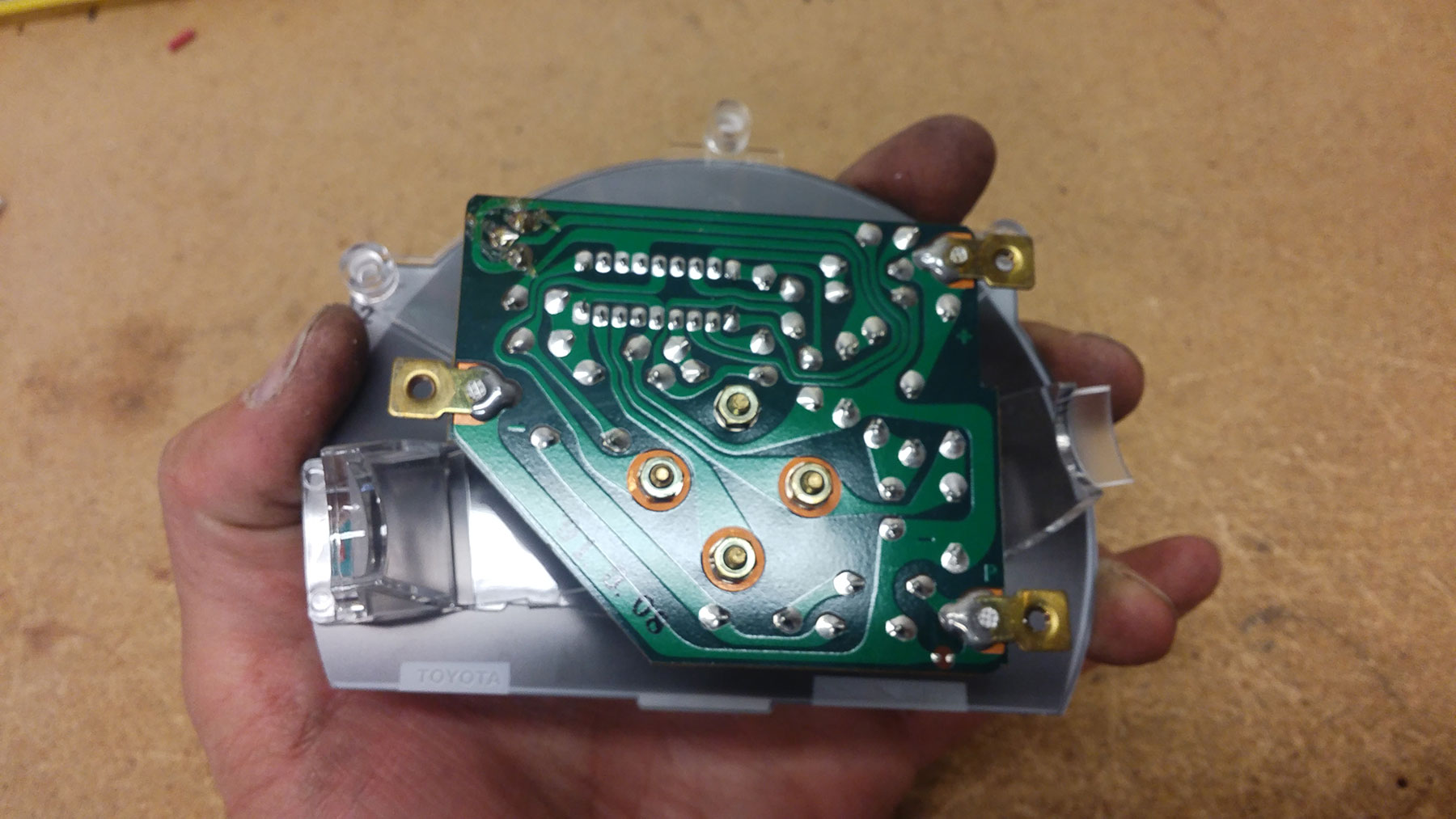
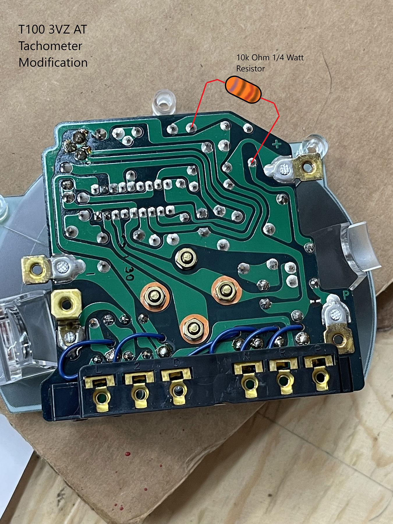
ALTERNATOR WIRING
- Watch our video to learn more about battery, alternator, and starter wiring.
- 3VZ-E/22R-E recipient vehicles OR internally regulated carbureted vehicles: Connect the original vehicle alternator connector and cable directly to the alternator. In some cases the original vehicle’s alternator connector is a direct plug-in. If the connector is different, the 3-wire connector from the 5VZ alternator can be spliced directly in place of the original vehicle’s alternator wiring connector. Simply cut the old connector from the lead and splice the 3 wires to the 5VZ alternator connector/lead, matching wire colors. The white is often different in diameter, this is OK. The original alternator cable can simply be bolted to the 5VZ alternator. Do not use or connect any 5VZ alternator wiring (that is in the battery cable harness) when doing alternator wiring. See “Connections for alternator and starter trigger” sketch.
-
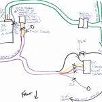
- Sketch of Alternator and Starter Trigger Connections
-

When Using An Internally Regulated Alternator In An Externally Regulated System
- Using the 5VZ alternator pigtail, connect pigtail to the alternator and route this harness to the driver side fender-well area.
- Find the original external alternator voltage regulator (IC Regulator) on the driver side inner fender-well area. Remove and discard the regulator. The following steps refer to the remaining regulator connector.
- Cut the appropriate wires from the original IC Regulator connector and splice the wires according to this chart:
- Original IC Regulator Connector » Newer Alternator Wiring
- Smaller white wire » Smaller white wire
- Red Wire » Red wire
- Yellow Wire » Yellow wire
- Large white cable » Large white cable
- Most externally regulated models (normally ’79-’83) have a “charge lamp relay”. This relay is normally located under the dash near the steering column. It will be labeled accordingly.
- If this relay exists, remove it. Cut this relay’s connector from the harness. Locate the yellow wire and the yellow w/ white stripe wire. Splice these 2 wires directly together. Insulate this connection.
- Insulate the 2 remaining wires, but DO NOT splice them.
When no charging system wiring is in place:
- Using the 5VZ alternator pigtail, connect pigtail to the alternator and route this harness to the driver side fender-well area. Wire the alternator accordingly:
- Red wire: “ignition on” 12V power – 12V when the ignition s/w is activated, fused at 10A – don’t give this constant power
- Small white wire: 12V battery power, direct connection to battery + terminal, fused at 7.5-10A.
- Yellow wire: ground signal for “charge warning lamp”. This provides a ground signal for a lamp in case of alternator failure.
- Large white cable: main alternator cable. This should be connected to the battery + terminal with an 80-100A fuse or fusible link in between. In most cases, an 8 or 6gauge cable can be used.
-

- Alternator Wiring When no Charging System Wiring is in Place

- If the battery is under-hood and re-located to the LH side: Find the power supply wire from the original fuse box, near the original battery location. This wire previously connected to the battery positive terminal. ORS offers an extension cable for this step, ORS-EC047. Using the ORS cable or 8-gauge cable, extend this power lead to reach the new battery location. If not using the ORS lead, be sure to install a fusible link of appropriate size at the end of this cable. Connect this lead to the battery positive terminal. Watch our video to learn more about battery, alternator, and starter wiring.
- Be sure the power supply wire that is routed in front of the radiator is loomed and properly secured below the radiator support. Excessive contact with the radiator when hot can damage this wiring. Use insulation or further fastening where necessary to prevent contact with the radiator.
- Important: If this step is not performed before engine is started, oil gauge damage may occur. Most 5VZ vehicles come standard with an oil pressure switch to operate a light on the dash. Many older vehicles had a gauge in the instrument cluster, which used an oil sender. If the original vehicle has a gauge, replace the oil switch on the 5VZ engine with the oil sender from the original (22R or 3.0L work) engine. It will thread straight in (but may require splicing the old connector to the engine harness). If a new oil sender is needed, Toyota PN 83520-34010 (1997 T100 5VZ SR5 application) will work well. See pics 56 & 57
-
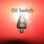
- Pic 56 – Oil Switch
-
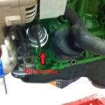
- Pic 57 – Oil Sender
-
- Note: In some cases there are two short wires departing the ORS harness labeled “Diagnostic Leads” or ”Cruise Control Diagnostic Leads”, labeled “TC” and “TS”. These are simply provided in case the need arises to pull trouble codes from the original ABS or Cruise Control systems. In the ORS Engine wiring, these check points are provided at the ‘Diagnostic’ connection on the LH side of intake plenum.
- Go through all wiring and be sure that all wires are routed properly and securely fastened. Be sure that all wires are clear of exhaust parts, engine parts, and sharp edges.
- Connect the battery negative terminal. Check the wiring supplemental instructions at the end of these instructions for any that apply.
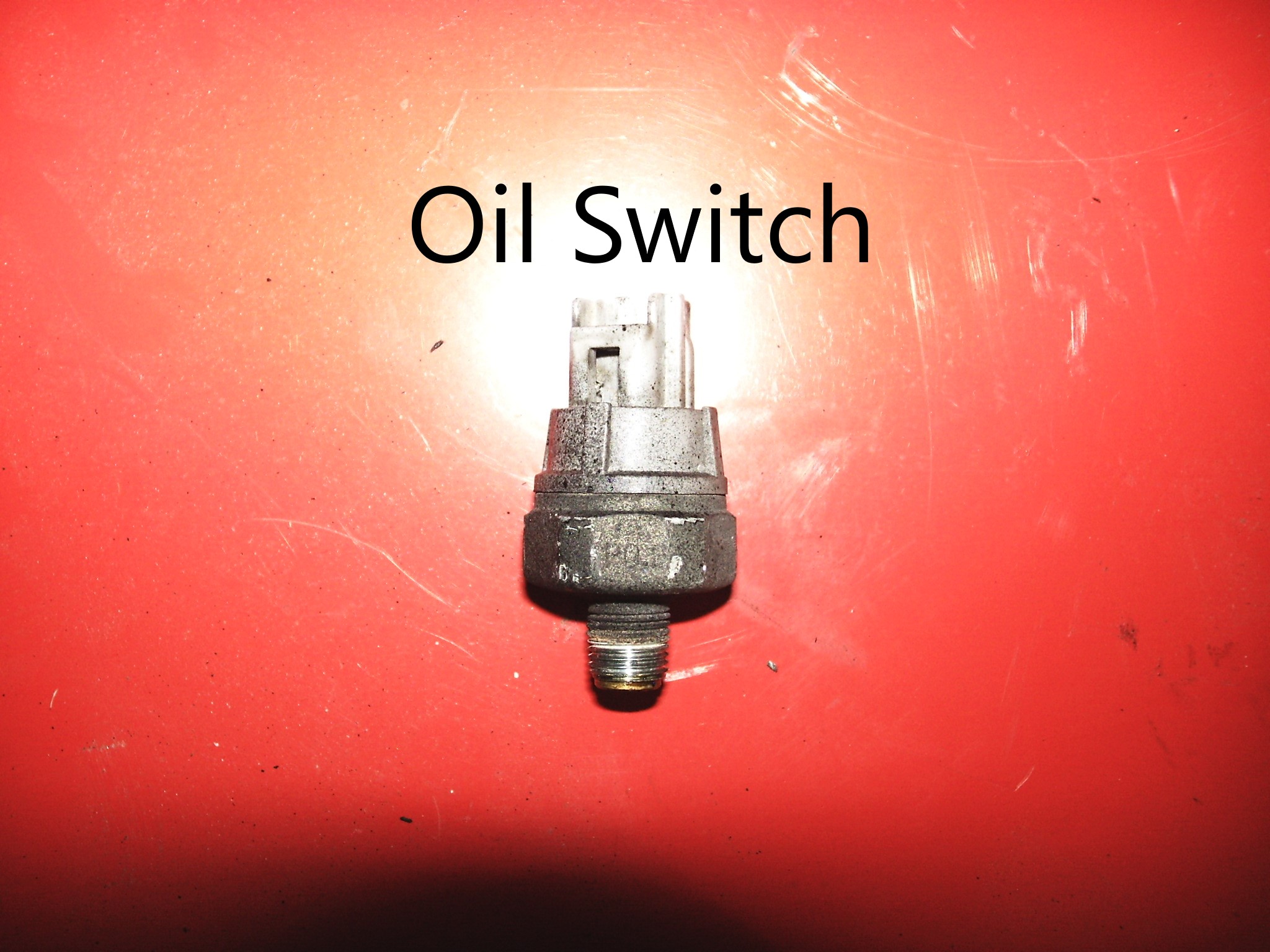
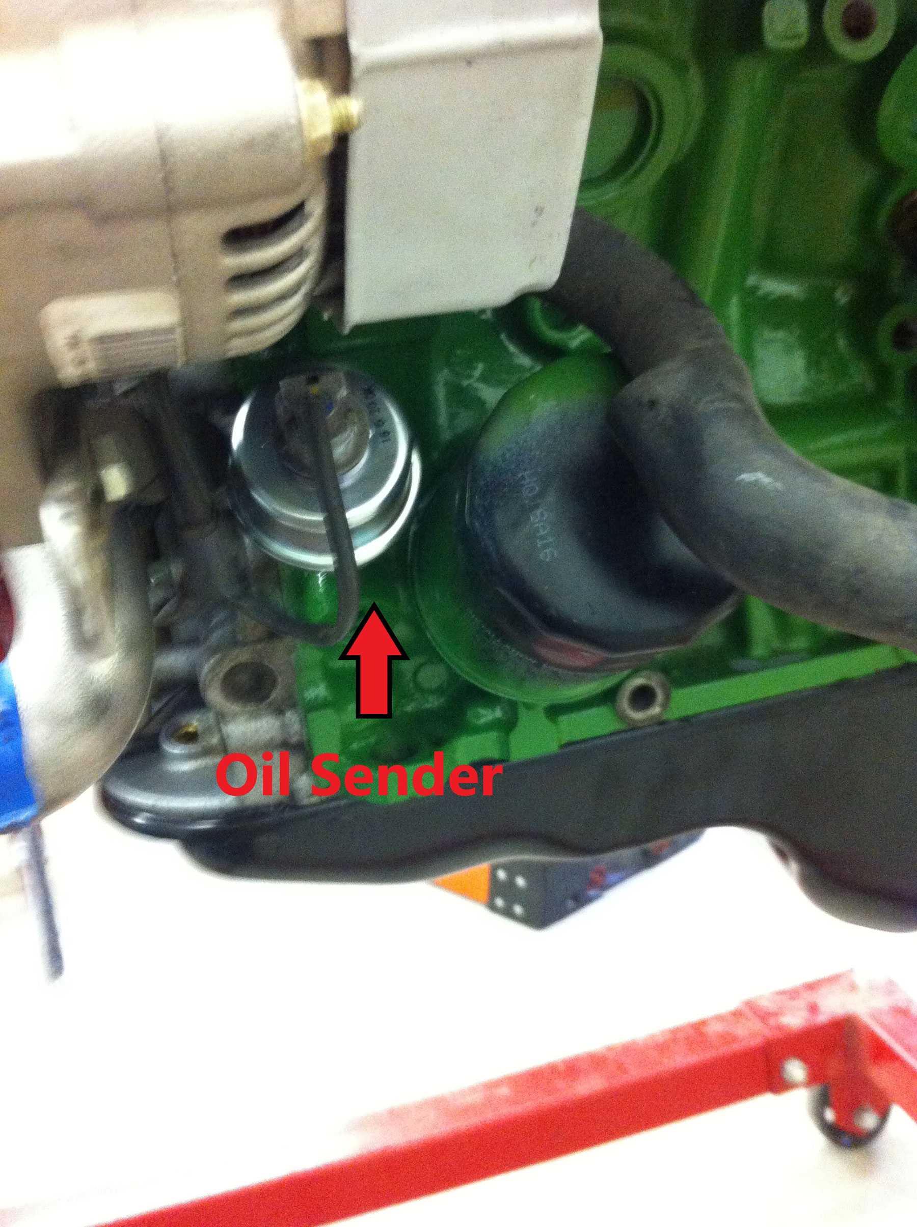
Under-Hood Completion
Radiator, Fan, Shroud, Belts, Hoses
- Install a 3VZ radiator and overflow tank in their original locations.
- Install the 5VZ or 3VZ fan clutch, the 5VZ or 3VZ fan, and 5VZ pulleys to the front of the 5VZ engine. There are 2 types of fans that came with the 3VZ. The most common is the enclosed type, with a ring around the blades. The second is the smaller, blade type. For safety and fit, ORS highly recommends using the smaller blade type, Toyota part # 16361-65020, not the enclosed type.
- Install the drive belts using proper tension (a bit tighter on a new belt).
- Install a 3VZ fan shroud. The opening in the shroud may need trimming on the LH side to clear the engine fan. In this case the lower cover on the shroud will no longer fit; we have found this will not adversely affect the performance of the radiator. We do NOT recommend cutting/trimming fan blade. See pic 58a & 58b.
-
- Pic 58a – Fan shroud trimming to fit 5VZ fan
-
- Pic 58b – Fan shroud trimming to fit 5VZ fan
-
- The lower radiator hose can be done one of two ways:
- The 5VZ thermostat housing (lower hose neck) can be left in place. The ORS lower radiator hose (or one like it) can be installed w/ the 3VZ radiator.
- The 3VZ thermostat housing can be installed. This would allow the use of the 3VZ lower radiator hose. In this case, the hose will contact the lower alternator bracket; shield and insulate the hose.
- Install the upper and lower radiator hoses and clamps.
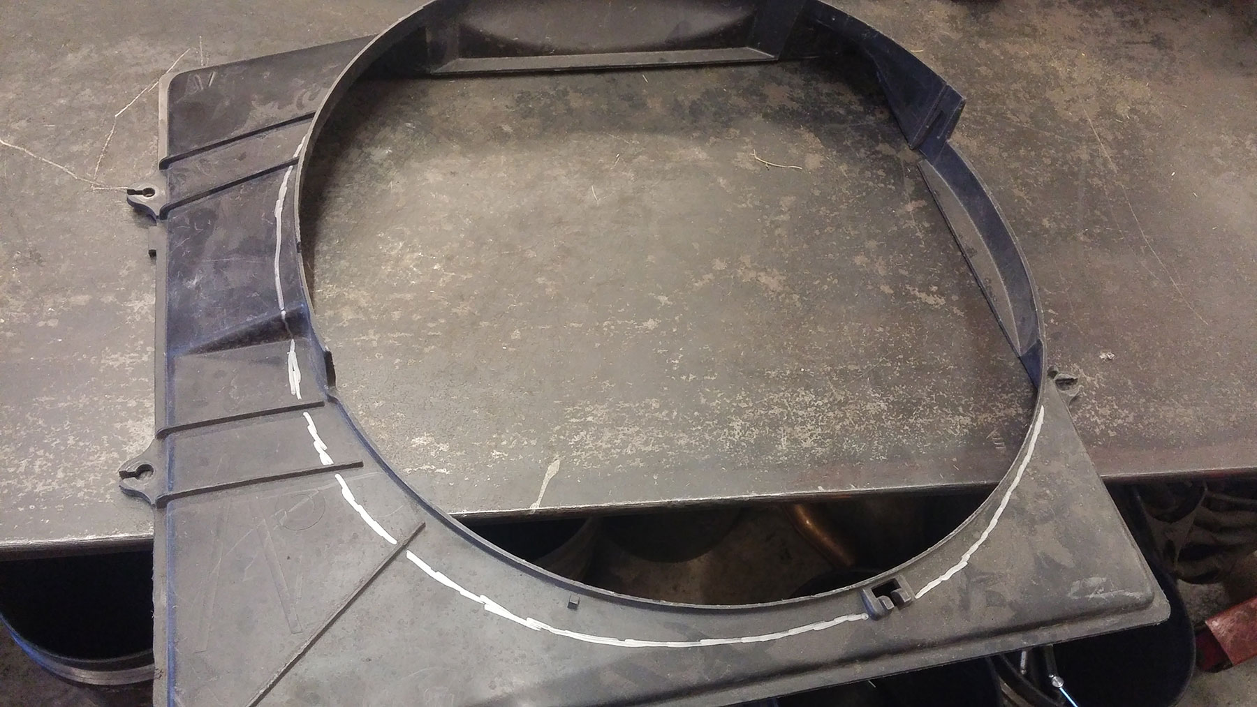
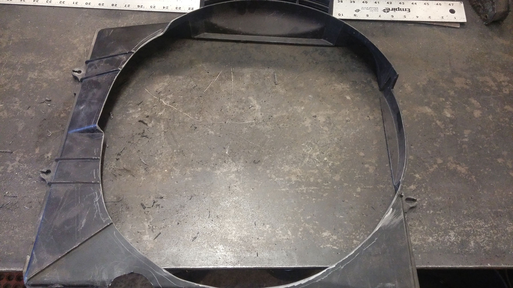
A/C System (if applicable)
- If the vehicle was originally equipped with Air Conditioning, we recommend utilizing the original A/C system. The system will remain un-changed, except the A/C compressor in some cases. Many original 3VZ compressors can be left in the vehicle during the swap and the system charge can remain in the system. This is done by unbolting the compressor from the 3VZ and leaving in the vehicle. If opening the A/C system, ORS recommends that the A/C system is evacuated and charged by a professional.
- Here are a few ways to complete the A/C system:
- Use the donor 5VZ A/C compressor. In some cases, normally 93-95 3VZ vehicles, the donor A/C will connect directly to the original high and low-pressure hoses. In this case, bolt the hoses directly to the donor compressor. If the original hoses will not bolt up, swap the (fitting bulkhead) from the original A/C compressor to the new one. This will allow the hoses to bolt up.
- Use the recipient/original 3VZ compressor. In this case, the compressor can be left in the vehicle if desired (no need to discharge system). Swap the magnetic clutch assembly from the donor 5VZ A/C compressor onto the original 3VZ compressor. If both are OEM compressors, this will be a direct-fit. Be sure to keep the shim installed between clutch and compressor housing. See pic #58
-
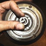
- Pic 58 – Shim under A/C Magnetic Clutch
-
- 22R-E vehicles: in many cases the donor 5VZ A/C compressor will be required. This may also require that custom high/low-pressure hoses are built to fit the new compressor. We recommend using a set of donor and recipient hoses to do this. Fasten the recipient hoses to the body-side connections, then fasten the donor hoses to the compressor. Cut and tape the hoses where they would join to form one hose. The mock-up hoses can then be brought to a custom hose/hydraulic shop as an example of the custom hoses needed.
- Pull vacuum on the system and check for leaks. Add the appropriate refrigerant oil and charge the A/C system with refrigerant.
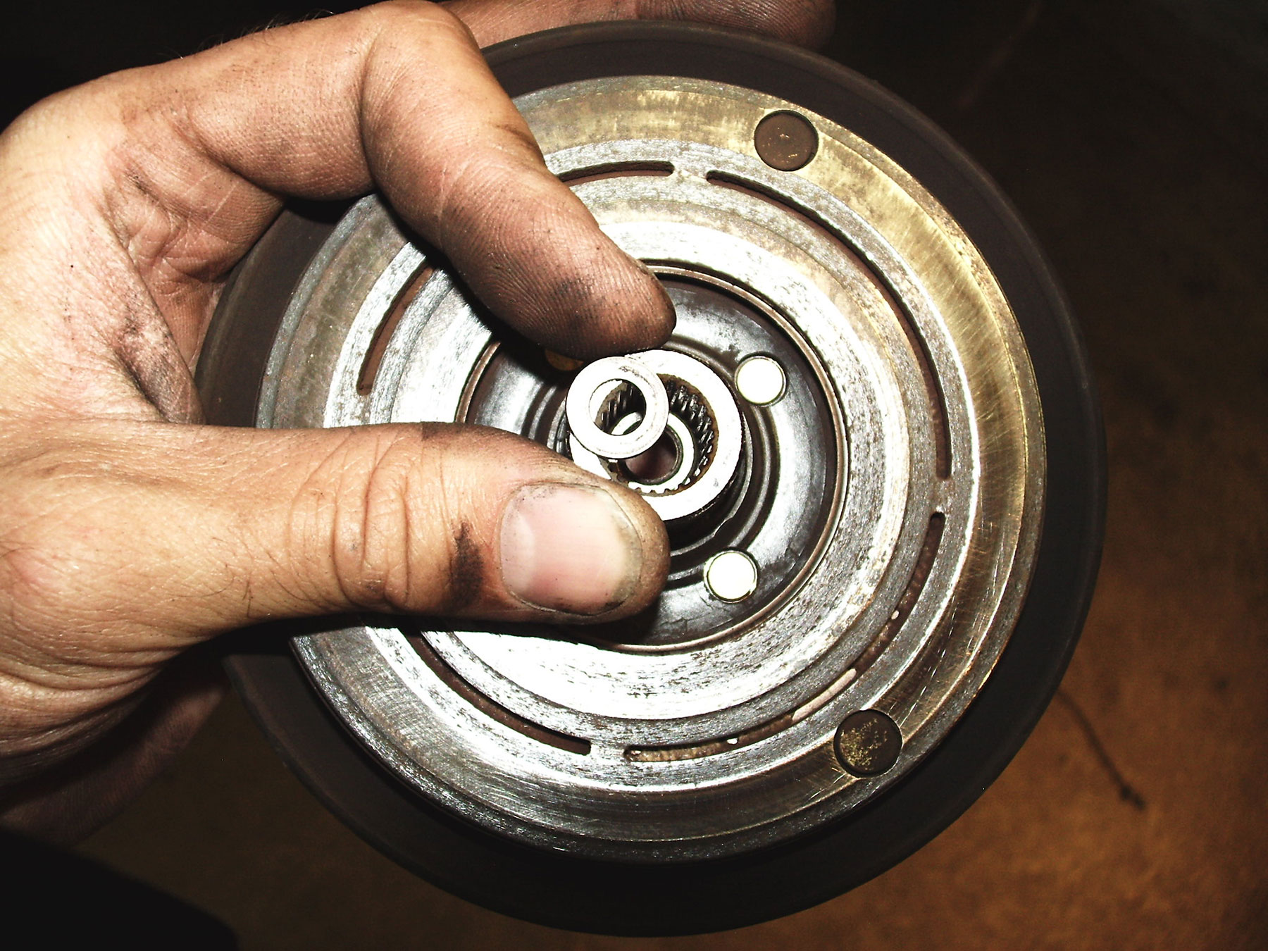
Hood Clearance
In most cases the 3.4L 5VZ will not fit under the hood; clearance will vary by vehicle. Normally the engine cannot be lowered to fit the hood due to suspension/steering/differential clearance. There are two common solutions to gain the clearance needed:
- Install a body lift. The 85-88 Truck and 85-89 4Runner applications normally require a 2” body lift. The 89-95 Truck and 90-95 4Runner applications normally require at least a 1” body lift.
- Clearance/modify the hood to fit. Sometimes this only involves cutting some bracing from the under-side of the hood, normally this also requires a small hole in the hood panel. We recommend covering the hole with a hood scoop. See hood clearance pics.
-
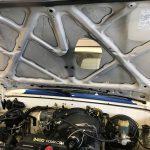
- Hood Clearance
-
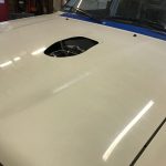
- Hood Clearance
-
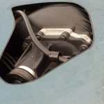
- Hood Clearance
-
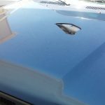
- Hood Clearance
-

- Hood Clearance
-

- Hood Clearance
-
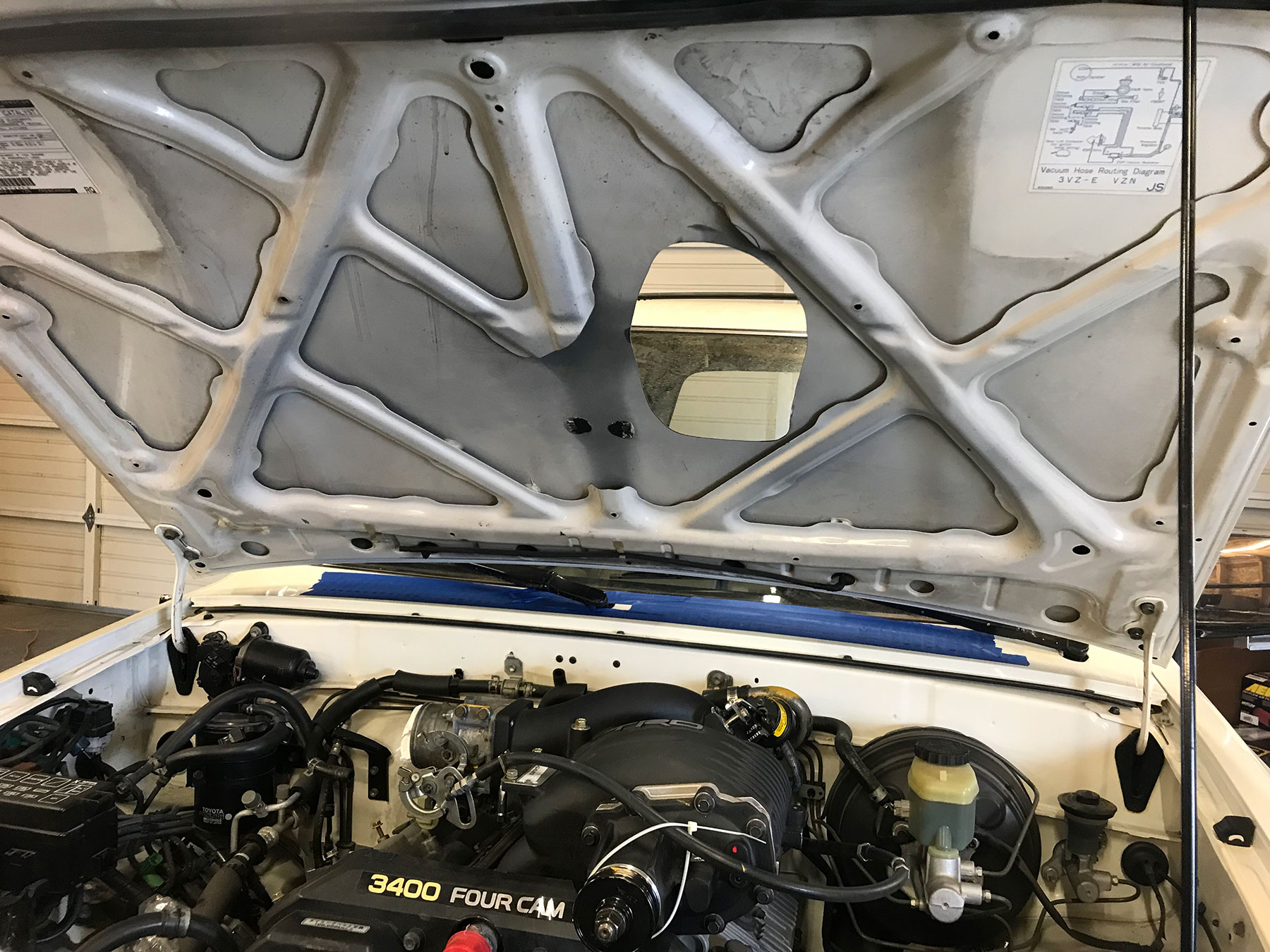
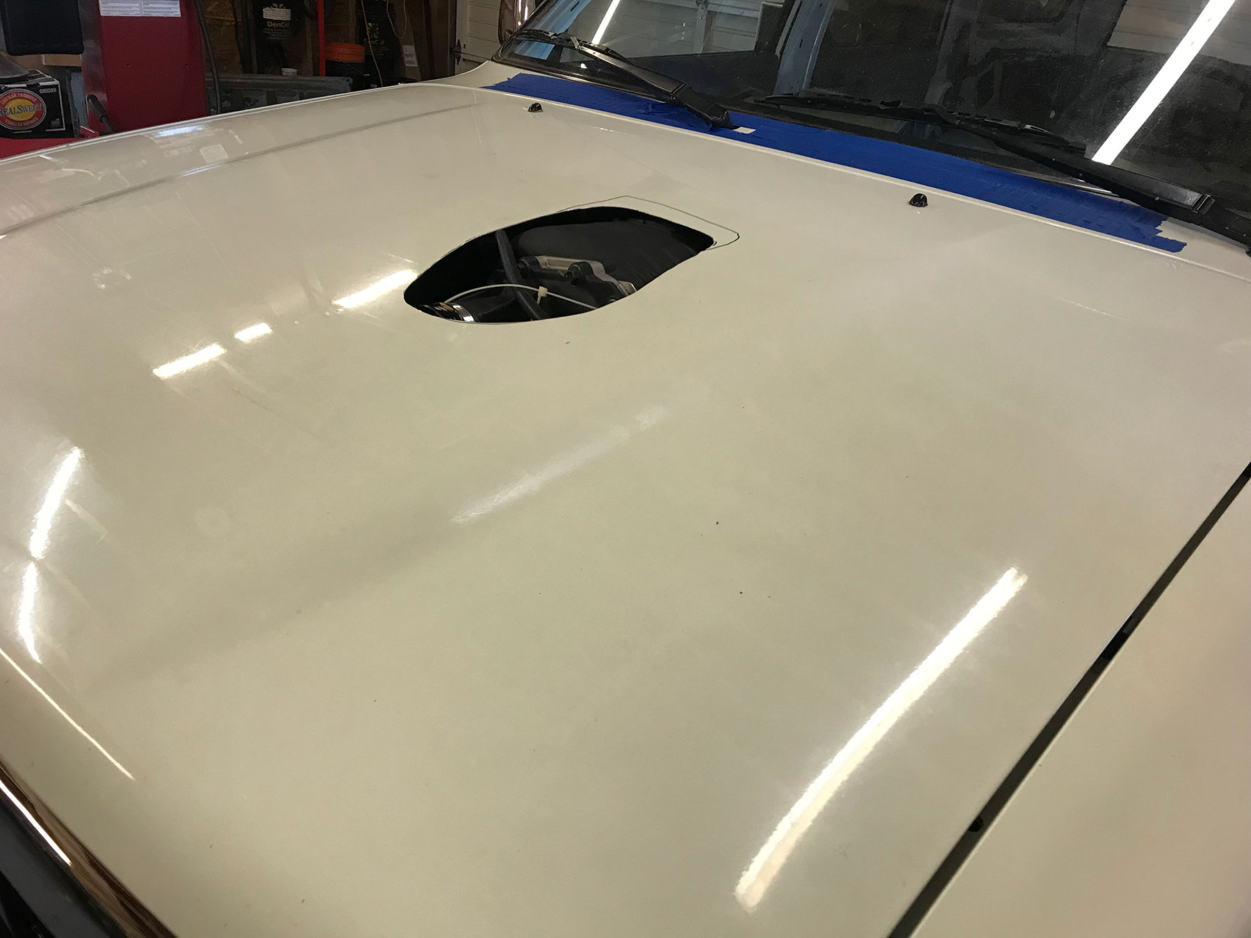
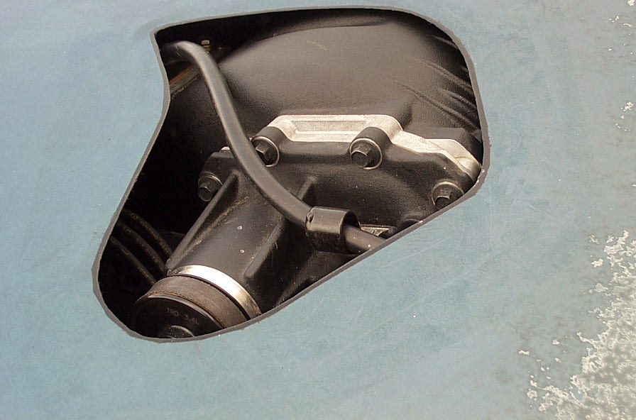
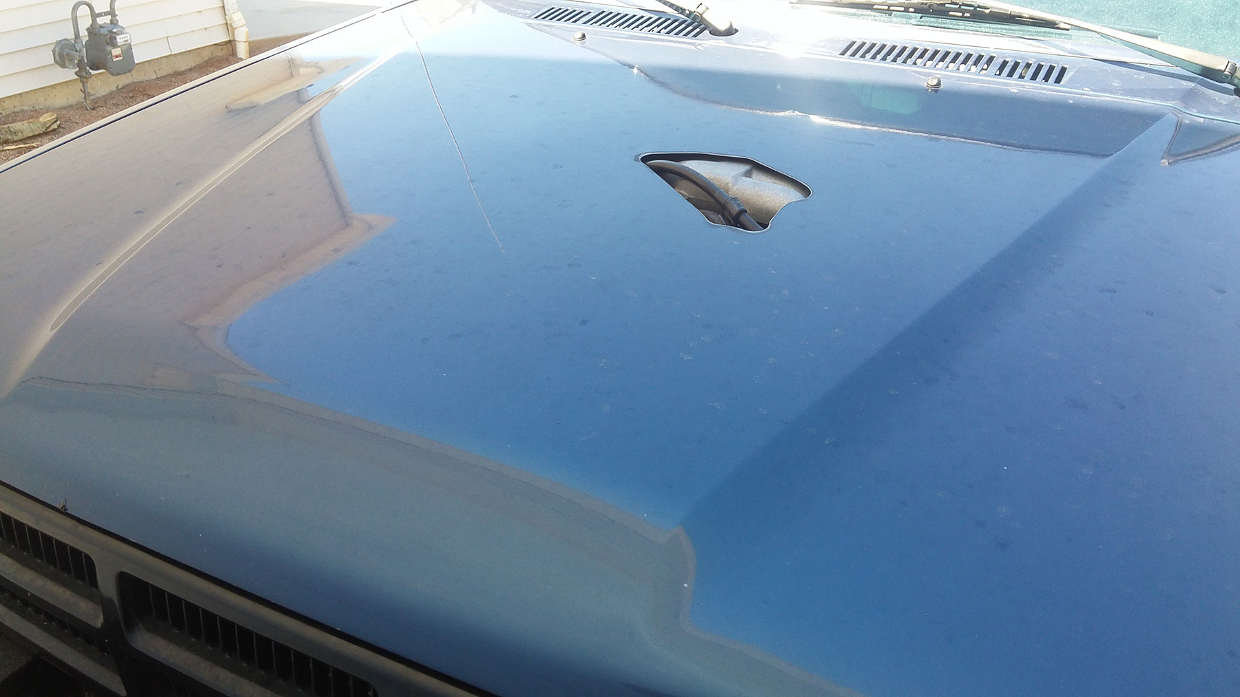

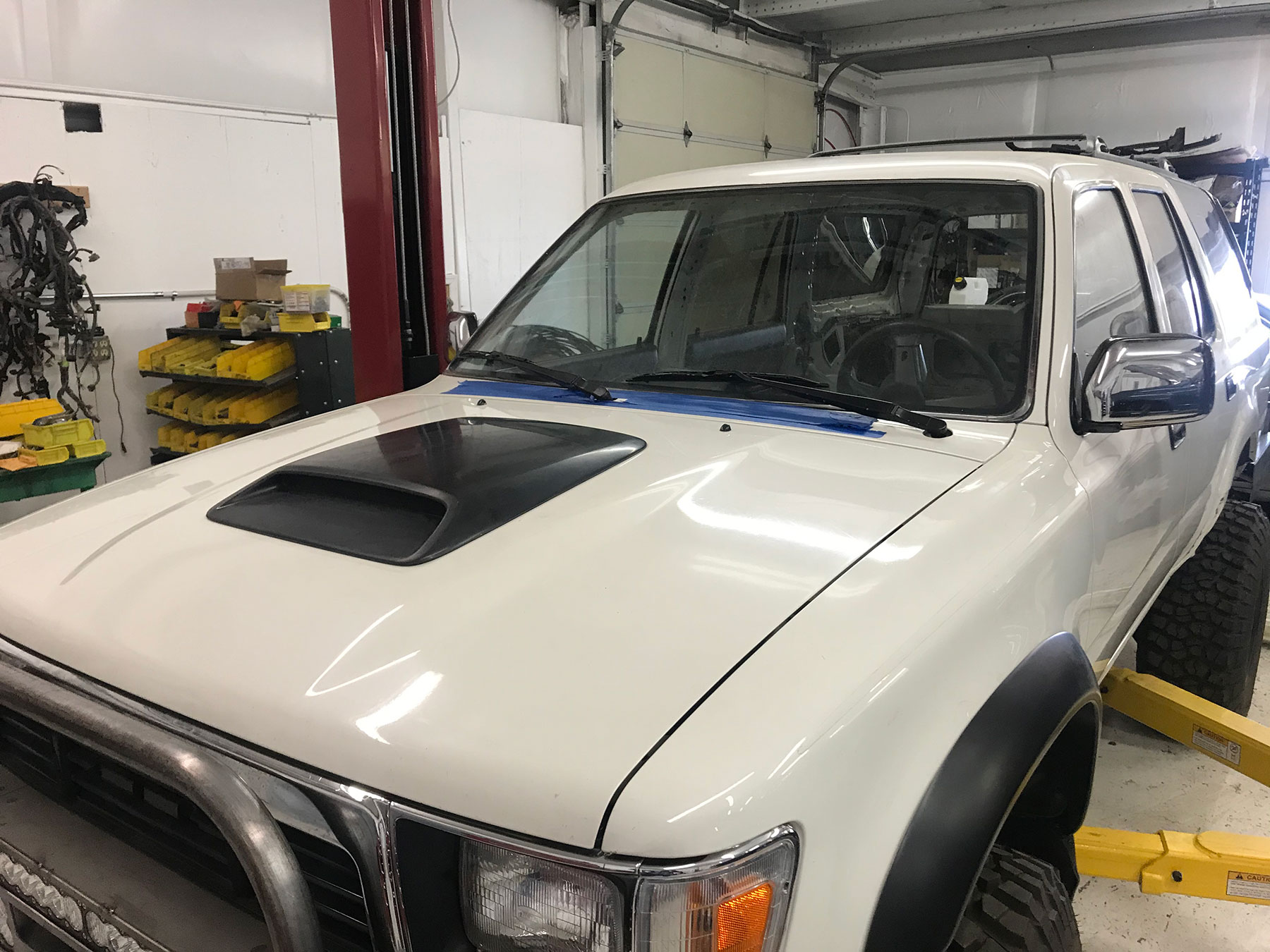
Finish work
- Check all hose and wire routing. Be sure hoses and wires are securely fastened and not against sharp edges, moving parts or not too close to exhaust.
- Fill engine oil, cooling system, power steering and transmission fluid (if applicable).
- Bleed the power steering system. We recommend raising the front tires off the ground and turning the steering wheel lock-to-lock several times, filling the reservoir as needed (engine OFF). After the engine has been started, it may be necessary to raise the front tires from the ground again and repeat this process with the engine running to fully bleed the power steering.
- Be sure to wear safety glasses for the next few steps!! Start the engine and bleed the cooling system:
- We recommend using a coolant fill funnel on the top of the radiator, leaving it half full until the system is bled.
- Another option is keeping the radiator full, with the cap removed, and removing the highest heater hose. Once coolant starts to run from the disconnected heater hose, re-install the heater hose.
- While the engine running check for any leaks. Once the cooling system is bled, install the radiator cap. Monitor engine temp, be sure the engine warms up to operating temp, maintains a safe temperature and that the thermostat has opened (both upper and lower hoses warm to touch).
Instruction Supplements
Review the titles on the following supplements and follow any that apply:
Wiring Supplements
A/C on Originally Equipped 3VZ 4×4 A/T Models
*On some 4WD models equipped originally equipped with the 3.0L engine and an automatic transmission, the A/C system contains a relay called the ‘A/C Cut Relay’. This relay is mounted near the heater/evaporator box. It can be accessed by removing the glove box. It is normally labeled ‘cut relay’ or ‘a/c cut relay’. When performing the 3.4L engine swap:
- Remove and discard the A/C Cut Relay
- Install the provided jumper connector in place of the relay (jumper provided with wire harness order).
This must normally be done before the A/C amplifier will operate the A/C compressor clutch.
Cruise Control Wiring Supplement for ETCS (Electronic Throttle Control System) donor vehicles only
*****NOTICE TO CUSTOMER: These instructions are only meant as a supplement to the original instructions. This supplement only pertains to conversions using donor vehicles w/ the Electronic Throttle Control System (ETCS), and only when using the 3.4L 5VZ-FE cruise control system.
In this case, cruise control is operated by the engine computer and actuated by ETCS. To complete this circuit, the donor vehicle’s cruise control clutch switch (M/T applications) will be required and the cruise control main switch may be required, along with the described wire splicing.
- Route the ORS harness wire labeled ‘to stop light switch’ to the brake/stop light switch. Cut the indicated wire from the switch connection and splice the switch side of that wire to the ORS wire lead (leaving wire into body wiring open).
- Locate the wires in the ORS harness labeled ‘to cruise control switch..’. In this case, the original CC switch from the donor vehicle is required to operate this system. These wires will be spliced to the donor vehicle CC switch as they are labeled. Mount the switch to the steering column or a desired location.
- M/T applications: In the recipient vehicle, locate the switch on the clutch pedal bracket that is depressed when the clutch pedal is released. Remove this switch and replace w/ the same type switch from the donor vehicle – Toyota PN 88280-14030. This switch must be open with the clutch pedal depressed. Adjust the switch so that it does not interfere w/ clutch pedal travel. Route the ORS harness lead labeled ‘to cruise control clutch switch’ to this location and connect to this clutch switch.
- Locate the wires in the ORS harness labeled “to cruise control ECU….”. Route to the original CC ECU (normally in LH “kick-panel” area). Remove and discard the original CC ECU. Cut the appropriate wires from the original CC ECU connector and splice to the ORS wires as labeled. Be sure to splice to the wire end leading into the body harness.
Wiring Supplements, for Various Auto-Transmission Applications
For ADAPTER Harness ONLY – ’89-’95 4×4 Trucks/’90-’95 4Runner Using 3.0L A340H A/T and Transfer Case
Use illustration below
- Read all instructions before beginning installation. This is only a supplement to the original instructions.
- The use of the 3.0L transmission may cause a constant trouble code (check engine light) due to a speed sensor difference. In this case the vehicle will drive OK, but imperfect shifting will occur. This can be solved by using a T100 ECU w/ the proper donor vehicle parts.
- If wire colors or connections described in these instructions do not match your specific application, please call ORS, we will gladly assist.
- In most cases, the 3.0L neutral safety switch will connect to the 3.4L engine harness. If not, install a neutral safety switch from the donor (3.4L) vehicle. In this case, this switch will bolt to the transmission. Connect the neutral safety switch to the 3.4L engine harness.
- Locate the A/T oil temp sensor on the transmission; this will be near the park/neutral switch. The 3.4L engine harness will normally have a connector that will directly connect here. Connect the temp sensor. In some cases the connector will not match and the connector from the original (3.0L) engine harness must be spliced to the 3.4L engine harness. Contact ORS for specific wire colors if needed in this step.
Transfer Case Wiring:
- The 3.0L transfer case temp switch will no longer be used.
- The ‘4WD switch’ leads on the ORS harness should already be routed down to the RH side of transmission.
- Locate the 3.0L 4WD detection switch connector, located along the RH side of the transmission. This will be a blue 6-hole connector. Locate the corresponding connector on the 3.0L engine harness. Cut this connector from the 3.0L engine harness with sufficient wire lead left. Splice the ORS harness to the 3.0L 4WD detection switch connector:
- ORS harness lead » 3.0L Engine Harness – 4WD detection switch connector
- “Ground” » white wire w/ black stripe
- “H4” » green wire w/ white stripe
- “L4” » yellow wire w/ red stripe
- Tape or seal the remaining wires in this connector and connect to the transfer case.
Transmission Solenoid Wiring:
- Locate the 3.0L solenoid “main” connector. This is a white 6-hole connector on the exterior of the transmission with wires leading into the transmission. Locate the corresponding connector on the 3.0L engine harness. Cut this connector from the 3.0L engine harness with sufficient wire lead remaining.
- Locate the solenoid connector on the 3.4L engine harness. This is normally a black 3-hole connector. On the back of this connector, use the engraved numbers to identify pin # 1, 2, and 3. Label the wires accordingly. Cut this connector from the 3.4L harness.
- Locate the 2-wire black connector on the 3.4L engine harness for the speed sensor. One wire should be yellow w/ red stripe or brown w/ red stripe. The other wire should be brown or white w/ red stripe. Cut this connector from the 3.4L harness.
- Splice the 3.0L solenoid connector to the 3.4L engine harness solenoid wires:
- 3.0L connector » 3.4L engine harness – solenoid connector wires
- White wire » pin # 1
- Black wire » pin # 2
- Yellow wire w/ black stripe » pin # 3
- 3.0L connector » 3.4L engine harness – speed sensor connector wires
- Brown wire w/ red stripe » yellow wire w/ red stripe or brown wire w/ red stripe
- Seal w/ tape, not used » brown wire or white wire w/ red stripe
- 3.0L connector » 3.4L engine harness – solenoid connector wires
- Splice the 3.0L solenoid connector to the ORS harness wire lead:
- 3.0L connector » ORS conversion harness
- Green wire w/ red stripe » lead labeled ‘to S4 solenoid wire’
- 3.0L connector » ORS conversion harness
- If applicable, 3.0L connector
- Brown wire w/ black stripe » connect to body ground or transmission case
This completes the custom wiring required for the 90-95 3.0L A/T.
-
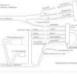
- Wiring Layout For Using 3.0L Transmission & Transfer Case with ORS Conversion Wiring Harness
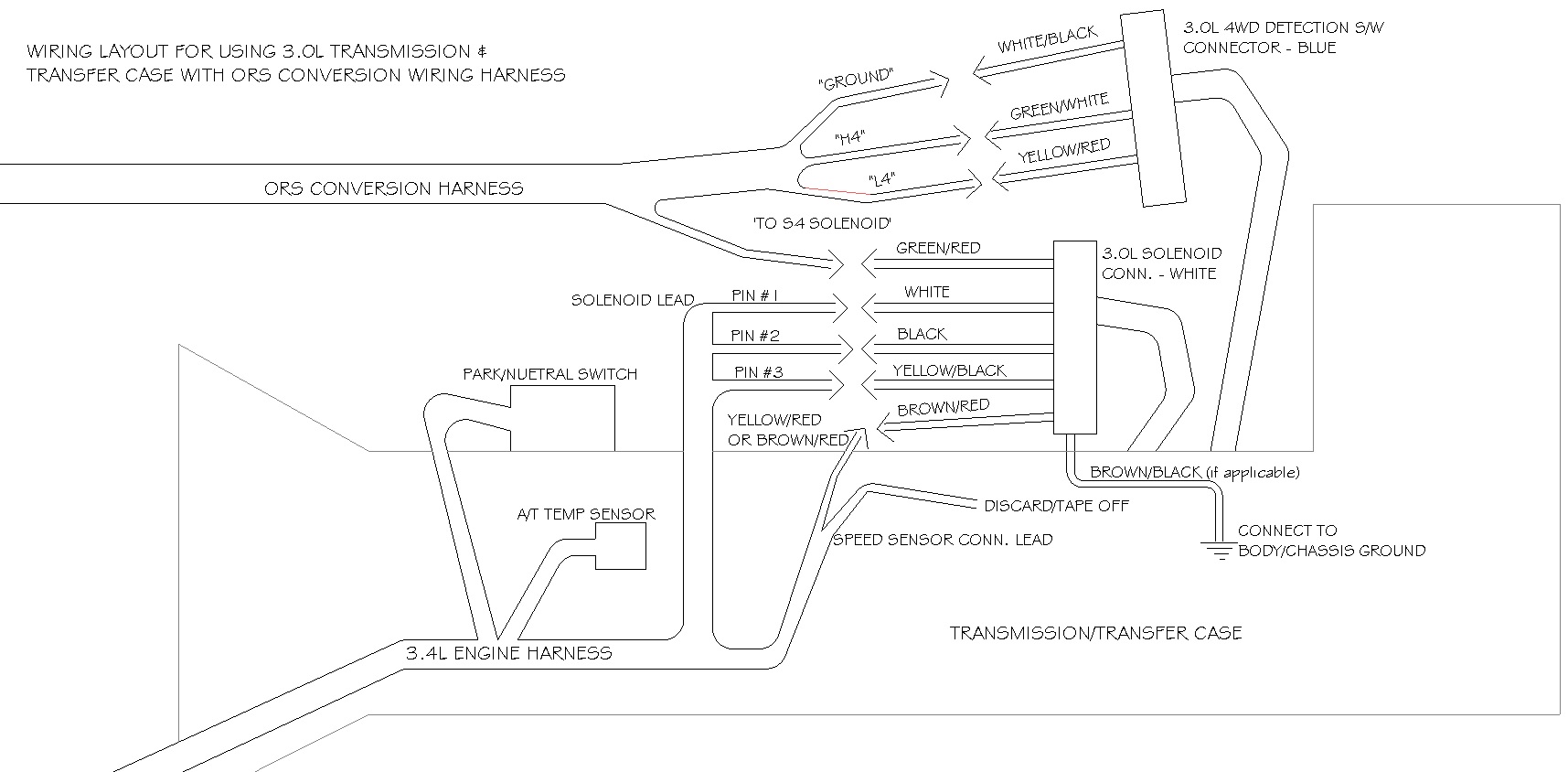
For ADAPTER Harness ONLY – ’85-’88 4×4 Trucks/’85-’89 4Runner Using A340H A/T and Transfer Case
Use illustration below
- Read all instructions before beginning installation. This is only a supplement to the original instructions.
- The use of the A340H transmission may cause a constant trouble code (check engine light) due to a speed sensor difference. In this case the vehicle will drive OK, but imperfect shifting will occur. This can be solved by using a T100 ECU from the proper application (contact ORS).
- If wire colors or connections described in these instructions do not match your specific application, please call ORS, we will gladly assist.
- If the recipient vehicle’s ‘ENGINE’ fuse (LH kick panel, lower center) is a 15A fuse, install a 10A fuse in its place.
- In some cases, the A340H park/neutral switch will connect to the donor (5VZ-FE/3RZ-FE) engine wire harness. If not, install a park/neutral switch from the donor application. Connect the park/neutral switch to the donor engine wire harness.
- Locate the A/T oil temp sensor on the transmission; this will be near the park/neutral switch. Locate the A/T oil temp connector on the donor engine wire harness (2-wire). If possible, connect. In some cases the connector housing will not match and the connector from the original (3VZ-E/22R-E) engine wire harness must be spliced to the donor engine wire harness. If so:
- A340H Connector » Donor engine wire harness
- Green wire w/ black stripe » Violet wire w/ yellow stripe
- Green/yellow or Light green/red » Blue/black
- A340H Connector » Donor engine wire harness
Transfer Case Wiring:
- The ‘4WD indicator/detection switch’ leads on the ORS wire harness should already be routed down to the RH side of transmission.
- Locate the A340H 4WD indicator/detection switch connector, located along the RH side of the transmission. This will be a white 4-hole or blue 6-hole connector. Locate the corresponding connector on the original (22R-E/3VZ-E) engine wire harness. Cut this connector from the original engine wire harness with sufficient wire lead remaining. Splice the ORS wire leads to the A340H (original) 4WD indicator/detection switch connector:
- ORS harness wire » Original Engine Harness – 4WD detection switch connector
- “Ground” » white wire w/ black stripe
- “H4” » light green wire
- “L4” » yellow wire w/ red or blue stripe
- ORS harness wire » Original Engine Harness – 4WD detection switch connector
- Connect this connector to the A340H 4WD indicator/detection switch connector.
Transmission Solenoid Wiring:
- Locate the A340H solenoid “main” connector. This is a white 6-hole connector on the exterior of the transmission with wires leading into the transmission. Locate the corresponding connector on the original engine wire harness. Cut this connector from the original engine wire harness with sufficient wire lead remaining.
- Locate the solenoid connector on the donor engine wire harness. This is normally a black 3-hole connector. On the back of this connector, use the engraved numbers to identify pin # 1, 2, and 3. Label the wires accordingly. Cut this connector from the donor engine wire harness.
- Locate the 2-wire black connector on the donor engine wire harness for the speed sensor. One wire should be yellow w/ red stripe or brown w/ red stripe. The other wire should be brown or white w/ red stripe. Cut this connector from the donor engine wire harness.
- Splice the A340H solenoid connector to the donor engine wire harness solenoid wires:
- A340H connector » donor engine wire harness – solenoid connector wires
- White wire » pin # 1
- Black wire » pin # 2
- Yellow wire » pin # 3
- A340H connector » donor engine harness – speed sensor connector wires
- Black wire w/ red stripe » yellow wire w/ red stripe OR brown wire w/ red stripe
- Seal w/ tape, not used » brown wire or white wire w/ red stripe
- A340H connector » donor engine wire harness – solenoid connector wires
- Splice the A340H solenoid connector to the ORS harness wire lead:
- A340H connector » ORS conversion harness
- Gray OR Red wire w/ blue stripe » lead labeled ‘to S4 solenoid wire’
- A340H connector » ORS conversion harness
- If applicable, A340H connector
- Brown wire OR white w/ black stripe » connect to body ground or transmission case
-
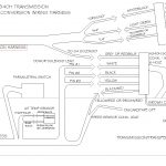
- Wiring Layout For Early A340H Transmission & Transfer Case with ORS Conversion Wiring Harness
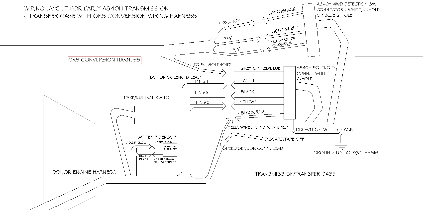
Automatic Transmission Applications When Using DONOR Floor Shifter
- A late model floor-shifter assembly from the donor vehicle can be used with this conversion. The following steps pertain to wiring that shifter.
- If the ORS conversion harness contains a lead labeled “to O/D switch”, skip the next step.
- Locate the original connector for the O/D off switch on the center floor-board, near the shifter. The two wire colors necessary are normally yellow-green and white-black. Locate the 2 white wires from the overdrive switch in the new shifter from the donor vehicle. They will be routed from the shifter handle. Connect these wires to the original O/D switch wires. Orientation of these wires does not matter. These can be spliced directly, but we suggest using some sort of connector. Skip the next step
- If the conversion harness contains a lead labeled “to O/D switch”, route this lead under the dashboard to the center floorboard near the shifter. Locate the original connector for the O/D off switch on the center floor-board near the shifter. The two wire colors necessary are normally yellow-green and white-black. Locate the 2 white wires from the overdrive switch in the new shifter from the donor vehicle. They will be routed from the shifter handle. Connect one white wire from the shifter to the ORS conversion harness lead labeled “to O/D switch”. Connect the other white wire to the white-black wire from the original O/D switch, or body ground. The yellow-green wire will be left disconnected. Wrap the end or this wire with tape or simply leave it inside its connector to prevent any possible shorting.
- Locate the original illumination power wires for the shifter assembly, also on the center floorboard, near the previous connector. The wire colors necessary are normally green and white-green or red-black. Locate the 2 white wires that power the shifter assembly illumination in the donor vehicle’s shifter. Connect one white wire to the green wire. Connect the other white wire to the white-green or red-black. Once again, we suggest the use of connectors.
- Note: Starting in 2000, many models used a ‘momentary’ OD Off switch, which is not compatible with the older type switches. If the OD Off function does not work, the use of a ‘momentary’ style switch (matching year/model of the computer) may be required.
When Installing 5VZ/3RZ A/T Into A43D Vehicles OR Originally M/T Vehicles
- This applies to vehicles that were originally Manual-Transmission-equipped or had a non-electronic transmission (such as A43D). A couple of components were added to the ORS Harness (the ECT switch and the AT temp lamp), and sometimes and O/D Off switch. Mount the ECT Switch, O/D switch, and the AT temp lamp where desired. When the ECT switch is turned on, it will modify the electronic shift pattern to be more aggressive. This is ideal for towing or mountain driving. The AT temp lamp illuminates if the transmission fluid temp reaches a dangerous temperature. The O/D Off switch will disable Over-Drive (4th gear).
- Due to the column shift setup on a non-electronic A/T vehicle, the wires in the ORS Harness related to the “O/D Switch” will need to be routed to the steering column area.
- Locate and access the wiring from the original O/D Off Switch (2 wires) on or near the steering column. Cut the yellow/green wire from the original switch. Locate the wire in the ORS Harness labeled ‘To O/D Off Switch”. Splice the ‘to O/D Off Switch’ wire from the ORS harness into the yellow/green wire leading into the switch.
- Locate the wire in the ORS Harness labeled “to O/D Off Switch Connection, yellow/green wire”. Splice this wire into the other end of the yellow/green wire, leading down into the body wiring.
- Leave the while/black wire intact.
- Note: Starting in 2000, many models used a ‘momentary’ OD Off switch, which is not compatible with the older type switches. If the OD Off function does not work, the use of a ‘momentary’ style switch (matching year/model of the computer) may be required.
General Supplements
Mass Air Flow Meter Wiring Interchange
This procedure is necessary when using an air flow meter that does not match the engine harness application. 1995-1998 3.4L 5VZ models use the larger air flow meter (diameter of intake tubing), while 1999-2004 models use the smaller type that inserts into the side of the intake tubing.
Using a small pick, remove the white ‘lock bar’ from the front of the connector. Using the illustration as a guide, move the wires to the proper cavity in the connector. Install the lock bar back into the connector when finished.
The wire colors indicated below dictate the wire color first, then the stripe color.
For used/donor engine wire harness:
| 1995-1998 Pin-out | 1999-2004 Pin-out | |
|---|---|---|
| #5 | brown/white OR black/white | #2 |
| #2 | gray/red OR red/white | #3 |
| #3 | yellow/green | #4 |
| #4 | brown/black OR blue/black OR green/white | #5 |
For ORS Engine Conversion Wire Harness:
| 1995-1998 Pin-out | 1999-2004 Pin-out | |
|---|---|---|
| #5 | black | #2 |
| #2 | gray | #3 |
| #3 | yellow | #4 |
| #4 | brown | #5 |
*The red wire in #1 is left in place.
-
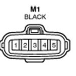
- M1 Connector Pins