MONSTER HARNESS
Install Notes
NOTICE TO CUSTOMER: If there is a problem suspected with the wiring harness, call ORS. DO NOT cut, alter, or dissect the ORS conversion harness. ORS accepts no responsibility for a harness that has been tampered with.
If wire colors or connections described in these instructions do not match your specific application, please call ORS, we will gladly assist.
- Do not connect the negative battery terminal until the wire harness installation is complete.
- Be sure the engine wiring harness is properly installed on the engine and all connectors are plugged in. Route the engine harness lead down the intended side of the engine and transmission. We highly recommend wrapping the wiring harness with heat tape or exhaust wrap anywhere it passes close to the exhaust.
- Connect the engine harness to the oxygen sensor lead(s).
- OBD2 engines: Depending on your application, there may only be one oxygen sensor connector in the engine harness. If only one is found, the other is contained in the ORS harness and will be connected later.
- Be sure the wiring harness is secured clear of exhaust parts or sharp edges to prevent damage.
- Route the engine wiring harness main loom into the interior. Choose a suitable mounting location for the ECU (engine computer).
- Place main part of ORS Monster harness where intended, normally near the ECU (engine computer) in the RH interior area.
- Hard-mount relay/fuse box(s), external relays and ECU. Keep these items away from moisture.
- Connect chassis or ‘body’ ground lead using a sturdy mounting bolt to a suitable ground location, normally an un-painted steel surface on the body/chassis.
- Connect the ORS Monster Harness to the ECU and engine wiring harness.
- Route the “under-hood” lead through the firewall to the engine bay. Connect to engine components as labeled, including the alternator (or the battery cable sub-harness). Important: Using the original insulator or an aftermarket insulator, insulate/cover the alternator post and cable.
- Mount the battery fuse block near the battery. Connect the leads and the battery terminal (if provided) to the battery positive post.
- The first couple inches of the main ‘battery positive’ lead may be constructed of fusible-link material. This small section will fail in the case of this cable shorting before the circuit breaker. If a short occurs (during the life of the harness), replace with the same size fusible link wire after the short is corrected.
- Route the main lead containing the switches, gauge provisions, etc. toward the driver side of the interior. Mount switches and connect/splice to the components as labeled.
- The ‘OBD2 Diagnostic Scanner Connection’ can be mounted in a convenient location and is only used to connect to an OBD2 scanner.
- Follow provided ‘battery cable’ (Front Battery, Rear Battery) diagram to add required battery cables and grounds.
- Connect the terminal x post ground lead to a chassis ground (if provided) and connect the negative battery terminal to the negative battery post.
- Open spaces in the fuse box can be utilized for additional circuits. Simply connect to the proper connection on the fuse box and install the desired fuse. The side of the fuse box labeled ‘Ignition’ will only provide 12V when the ignition switch is on. This is useful for circuits that should only be ‘on’ with the ignition switch on. The side of the fuse box labeled ‘Battery’ will provide 12v at all times. Be sure not to exceed the fuse rating written on or under the fuse box (normally 25A in the ignition box and 40a in the battery box) with any one single circuit. Delphi 280 series terminals and seals will work to add circuits to this fuse box. ORS can provide these parts if needed.
- Some ORS lighting circuits will not have a dedicated ground wire. In this case simply ground each lamp to the body/chassis where the lamp is mounted.
- When a Toyota-type vehicle speed sensor (VSS) is used, calibration of an aftermarket speedometer may be required. In this case, the Toyota vehicle speed sensor outputs a 4-pulse digital, rectangular-wave signal pattern.
- Additionally, this is the same signal used with any Toyota engine computer. However, Toyota provides a ‘filtered’ signal to the computer, by way of the speedometer assembly or the ABS computer. The ORS Monster harness will use the raw signal from the VSS into the engine computer (unless a Toyota speedometer is in use), which often works. If a Toyota speedometer is not used in your setup and a vehicle speed sensor trouble code occurs (and the VSS and circuit are OK), the use of a signal interpreter may be required. If so, we recommend Dakota Digital.
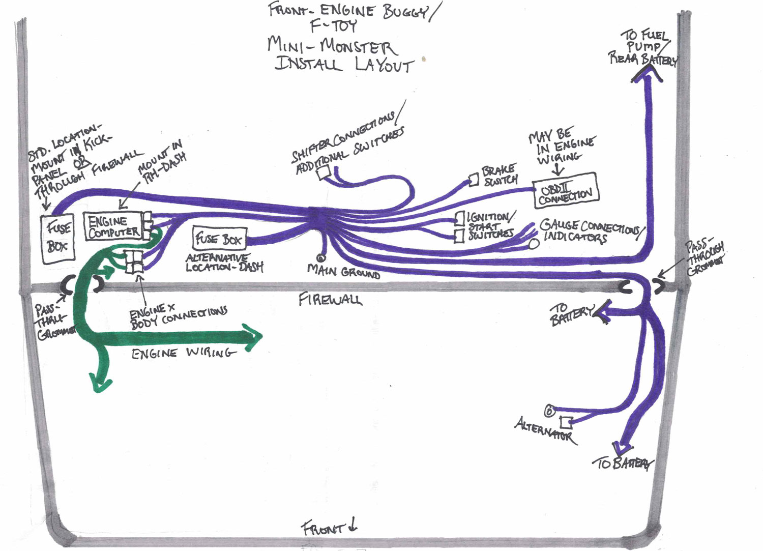
Mini-Monster Harness into Front Engine Buggy – Install Layout


