Install Instructions
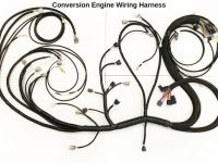
Conversion Engine Wiring Harness
5VZ-FE, 3RZ-FE, 22R-E Engines
*****NOTICE TO CUSTOMER: If there is a problem suspected with the wiring harness, call ORS. DO NOT cut, alter, or dissect the ORS conversion harness. ORS accepts no responsibility for a harness that has been tampered with.
If wire colors or connections described in these instructions do not match your specific application, please call ORS, we will gladly assist.
- ORS recommends the use of the 3RZ/5VZ battery harness for applications with the battery under the hood. This is the harness that connects the battery terminals to the starter and engine grounds in the donor vehicle. The starter wiring also contained in this harness. If this harness is damaged or not available, ORS offers a conversion replacement for this harness, PN ORS-EC046 for 5VZ applications and ORS-EC110 for 3RZ applications. Install this harness to the engine using the original configuration. Connect the engine ground cable and the starter terminal and cable. Install battery harness on engine. Do not connect the battery terminals at this time. If using the ORS Battery harness, refer to the provided ORS Battery Harness Installation Notes.
- In most cases, it will be necessary to remove the intake plenum from the engine. Place the ORS Engine Harness on the engine, starting w/ the large part of the harness along the topside of the back of the engine. Following the same basic routing of the original engine wire harness, install the ORS engine harness on the engine. Make all possible connections. Where necessary, secure harness using insulated closed clamps. Be sure harness is secured from contact with hot components, such as the EGR pipe.
- On 85-88 22R-E donors, mount the 22R-E Injector resistor on the RH fender well and connect to the ORS harness.
- On the 5VZ, route the transmission/O2 sensor section down the RH fender and under the RH side of the vehicle, along the transmission (follow brake and fuel lines). On 3RZ, route the transmission/O2 sensor section down the LH rear corner of engine, over the transmission and to transmission connections. On 22R-E engines, route the transmission/O2 sensor section from under the plenum, down the RH side of the transmission and along the floorboard. We highly recommend wrapping the harness with heat tape or exhaust wrap anywhere the harness passes close to the exhaust.
- Route the section of harness containing EVAP and battery connections to the LH fenderwell area.
- Route the “interior” section of ORS harness through the RH firewall hole into the interior. This is the section of the ORS harness that has the ECU and body connections.
- If applicable: In the interior, route the diagnostic lead under the dashboard to the LH side of the vehicle. Find a suitable location under the LH dashboard area and mount the diagnostic (OBDII) connector. This connector serves as the port for an OBDII diagnostic scanner.
- Connect the ORS harness ECU connectors to the ECU.
Steps 9-12 pertain to 22R-E/3VZ-E recipient vehicles:
- Connect the ORS harness to the vehicle body wiring harness. These are the white and gray or yellow connectors found in the RH side kick-panel (where original engine harness was removed).
- If applicable, for harnesses with leads labeled “to ECU CONN V”: locate the original ECU connector (yellow) still in the vehicle. Cut the appropriate colored wires from this connector and directly splice to the appropriate labeled wires in the ORS harness. Use the wire end that leads into the vehicle’s harness.
- If applicable on AT models: Route the leads labeled “to ECT or A/T ECU connector” to the connector from the original A/T ECU (computer). Splice the leads to the appropriate wires in the A/T ECU connector as labeled, connecting to the wire end that leads into vehicle harness. The original A/T or ECT ECU is not needed and can be discarded.
- If applicable, connect the lead labeled “injector resistor” to the original injector resistor connector on the RH side fender-well. Connect this lead to the original 1-wire connector. Splice/connect the lead labeled “to igniter black wire” to the original 22R-E coil/igniter connector (2-wire green on LH fenderwell), solid black wire.
Steps 13-20 pertain to ‘Stand-Alone’ recipient vehicles
- Secure the ‘body ground’ terminal near this section to a suitable body ground.
- Route the harness lead containing the check engine light, diagnostic port, gauge leads, start and ignition leads, and brake switch lead toward the LH side of the vehicle, inside the interior.
- Mount the check engine light in an appropriate location in the LH interior area.
- Connect the “ignition on” signal to an ignition power source. This will be a source that only provides 12V when the key/switch is in the ‘on’ and ‘start’ positions.
- Connect the “start signal” lead to a start power signal source. This will be a source that only provides 12V when the key/switch is in the start position, often found at the ignition switch. M/T applications: If the ORS harness does not have clutch safety switch wires, and the use the vehicle’s clutch safety circuit (if equipped) is desired, use the start trigger wire coming from the original start relay instead of the start wire at the ignition switch.
- Splice the wire labeled ‘brake light switch signal’ into the switching side of the brake light circuit. This will be the side of the switch that only provides 12V with the brake pedal depressed. This is often a green/white wire. The brake signal is not required but recommended.
- Connect the “speed sensor” wire to a speed sensor signal. This can be provided from an after-market speed sensor designated for Toyota applications. This will be a 4-pulse-per-revolution square-wave signal. Originally carbureted Toyota vehicles: this is provided in the original cluster, simply tee/splice to green blue wire in the rear of the instrument cluster.
- The wires labeled “tachometer”, “water temp”, and “oil pressure” are signals for the corresponding gauges. Connect these leads to their proper gauge sender wire. Toyota tachometers may require soldering a 10k ohm ¼ watt resistor into the back to function with the 3RZ. Refer to provided illustrations. Originally carbureted Toyota vehicles: tee/splice to corresponding wires in the rear of the original instrument cluster.
- If applicable: The ORS harness contains a lead labeled “tachometer”. If an aftermarket tachometer is used, this lead will provide the necessary RPM signal. If an aftermarket tachometer is not used, cover the end with tape or shrink-wrap and tape this lead to the side of the ORS harness. Note: If using the original tachometer, it is already pre-wired in the ORS harness.
- If applicable, certain 5VZ setups: The connection labeled “7th injector kit” is available for the use of a 7th Injector fuel kit, used to enhance a supercharger system. This connection is used for an easy interface to the 7th Injector sub-harness. Simply use the 7th injector connector w/ the wire pigtails to splice to the 7th Injector sub-harness, then connect this connector to the ORS engine harness. If a 7th Injector kit is not currently used, leave the 7th Injector connection cap (with small wire loops) in place and store the connector pigtail for future use.
- If applicable: The wire in the ORS harness labeled “to + illumination wire” is optional. It allows the ECU to detect electrical loads. Splice this wire into an illumination circuit in the interior, a wire that has 12v with the tail lamps on. These are often found at switch connectors, or the illumination for the cigarette lighter, and are often green.
- MT models: Connect the reverse light connection to the transmission. If the ORS harness has 2 wires labeled “reverse light switch”, cut and splice these wires into the reverse light switch on the side of the transmission. This switch is non-directional, meaning each wire has no specific match.
- AT models using donor transmission: Connect the ORS harness to the transmission P/N switch, solenoid, speed sensor and temp sensor.
- 3VZ 4×2 A/T models: The 4×2 automatic-transmission may not have a trans temp sensor installed from the factory. To satisfy the ECU an A/T temperature sensor will need to be installed in the transmission. We suggest obtaining a temp sensor from a donor or a 4×4 3VZ A/T application, or the donor application. There is normally a plug/provision for this sensor near the transmission cooler lines on the RH side of the transmission. That sensor will then plug into our new harness or donor engine wiring.
- AT models using A340H original transmission: Working on RH side of bell-housing: Connect the ORS harness to the transmission P/N switch and temp sensor. In most cases, the 3.0L neutral safety switch will connect to the 3.4L engine harness. Note: If the P/N switch connector is different, install a neutral safety switch from the donor (3.4L) vehicle. In this case, this switch will bolt to the transmission. Next, connect the white and black transmission connections to the original A340H trans sub-wire harness.
- If applicable: Cut and splice the leads labeled “4WD indicator switch” into the transfer case position switch. This switch is also non-directional. Be sure that all connections are secure and sealed. Also be sure the wiring harness is safely routed under the vehicle. If the 4WD indicator switch only has one wire, use the ORS light green wire, brown will not be needed.
- If applicable, connect the “speed sensor” connector to the vehicle speed sensor on the rear of the transfer case/transmission.
- Connect the ORS harness to the Oxygen Sensors (or A/F Ratio Sensor). The connection closer to the engine is for the upstream sensor, while the sensor further from the engine is for the downstream sensor. The upstream sensor will likely be routed over the transmission case, while the downstream sensor can be routed over the transmission or around the rear of the transmission. Be sure to secure the wiring and apply heat shield tape/material anywhere the wiring passes close to heat.
- If applicable, route the “fuel pump” lead to the fuel pump. Splice to the positive fuel pump wire, leading into the pump. This is usually a blue wire.
- Be sure the wiring harness is secured and clear of exhaust parts to prevent heat damage.
- Connect to the appropriate evaporative valves and vapor pressure sensor (EVAP). Use the provided EVAP hose diagram to identify the proper parts.
- 5VZ/3RZ: The lead labeled “starter” (under the hood) is ultimately connected to the smaller “trigger” terminal on the starter. This can be done one of two ways. 1) If using the 5VZ/3RZ battery harness: route the “starter” lead across the engine bay (in front of radiator), to the battery area. Cut the 4-pin (1-pin on T100 engines) connector from this harness (located near the battery terminals). Splice the wire labeled “starter” to the black wire in this connector. Be sure the connection is secure and sealed. 2) If not using the 3.4L/2.7L battery harness, route the “starter” lead to the starter. Directly connect this lead to the trigger terminal on the starter.
- Mount the 5VZ/3RZ/22R-E ECU. The brackets bolted to the side of the ECU share the same bolt pattern as all Toyota ECU’s. This allows the installer to share brackets from any ECU to help in the mounting process. Find a location near the passenger side kick-panel that will house the ECU. Be sure that the ORS wiring harness and the engine wiring harness leads will reach the ECU and plug in. If the vehicle does not have A/C it is possible to mount the ECU behind the glove box.
ALTERNATOR WIRING – for 3VZ-E/22R-E recipient vehicles (Stand-Alone recipient Alternator wiring at end of these instructions)
- Connect the original vehicle alternator connector and cable directly to the alternator. In some cases the original vehicle’s alternator connector is a direct plug-in. If the connector is different, the 3-wire connector from the 5VZ/3RZ alternator can be spliced directly to the original vehicle’s alternator wiring lead. Simply cut the old connector from the lead and splice the 3 wires to the 5VZ/3RZ alternator connector/lead, matching wire colors. The white is often different in diameter, this is OK. The original alternator cable can simply be bolted to the 5VZ/3RZ alternator. Do not use or connect any 5VZ/3RZ alternator wiring (that is in the battery cable harness) to the alternator or battery.
- If the battery is under-hood and re-located to the LH side: Find the power supply wire from the original fuse box, near the original battery location. This wire previously connected to the battery positive terminal. ORS offers an extension cable for this step, ORS-EC047. Using the ORS cable or 8-gauge cable, extend this power lead to reach the new battery location. If not using the ORS lead, be sure to install a fusible link of appropriate size at the end of this cable. Connect this lead to the battery positive terminal.
- Be sure the power supply wire that is routed in front of the radiator is loomed and properly secured below the radiator support. Excessive contact with the radiator when hot can damage this wiring. Use insulation or further fastening where necessary to prevent contact with the radiator.
- Important: If this step is not performed before engine is started, oil gauge damage may occur. Most 3.4L/2.7L vehicles come standard with an oil pressure switch to operate a light on the dash. Many older vehicles had a gauge in the instrument cluster, which used an oil sender. If the original vehicle has a gauge, replace the oil switch on the 5VZ/3RZ engine with the oil sender from the original (22R or 3.0L work) engine. It will thread straight in (but may require splicing the old connector to the engine harness). If a new oil sender is needed, Toyota PN 83520-34010 works very well.
- The tachometer will not work without modification (most cases). We have included an illustration that depicts soldering a 10k ohm resistor to the back of the tachometer. This is done after the instrument cluster has been split open and the tachometer individually removed. This solution was found on internet forums. We suggest searching pirate4x4.com, yotatech.com, or 4x4wire.com for more information on this modification.
- Go through all wiring and be sure that all wires are routed properly and securely fastened. Be sure that all wires are clear of exhaust parts, engine parts, and sharp edges.
- Connect the battery negative terminal. If no further supplements apply, the installation is complete.
Supplement for Automatic Transmission applications:
When using a late-model floor shifter
- A late model floor-shifter assembly from the donor vehicle can be used with this conversion. The following steps pertain to wiring that shifter.
- If the ORS conversion harness contains a lead labeled “to O/D switch”, skip the next step.
- Locate the original connector for the O/D off switch on the center floor-board, near the shifter. The two wire colors necessary are normally yellow-green and white-black. Locate the 2 white wires from the overdrive switch in the new shifter from the donor vehicle. They will be routed from the shifter handle. Connect these wires to the original O/D switch wires. Orientation of these wires does not matter. These can be spliced directly, but we suggest using some sort of connector. Skip the next step
- If the conversion harness contains a lead labeled “to O/D switch””, route this lead under the dashboard to the center floorboard near the shifter. Locate the original connector for the O/D off switch on the center floor-board near the shifter. The two wire colors necessary are normally yellow-green and white-black. Locate the 2 white wires from the overdrive switch in the new shifter from the donor vehicle. They will be routed from the shifter handle. Connect one white wire from the shifter to the ORS conversion harness lead labeled “to O/D switch”. Connect the other white wire to the white-black wire from the original O/D switch, or body ground. The yellow-green wire will be left disconnected. Wrap the end or this wire with tape or simply leave it inside its connector to prevent any possible shorting.
- Locate the original illumination power wires for the shifter assembly, also on the center floorboard, near the previous connector. The wire colors necessary are normally green and white-green or red-black. Locate the 2 white wires that power the shifter assembly illumination in the donor vehicle’s shifter. Connect one white wire to the green wire. Connect the other white wire to the white-green or red-black. Once again, we suggest the use of connectors.
- Note: Starting in 2000, many models used a ‘momentary’ OD Off switch, which is not compatible with the older type switches. If the OD Off function does not work, the use of a ‘momentary’ style switch (matching year/model of the computer) may be required.
Instruction Supplement
Installing 5VZ/3RZ A/T Into A43D Vehicles
- Since the original A43D transmission was not electronically controlled, a couple of components were added to the ORS Harness (the ECT switch and the AT temp lamp). Mount the ECT Switch and the AT temp lamp where desired. When the ECT switch is turned on, it will modify the electronic shift pattern to be more aggressive. This is ideal for towing or mountain driving. The AT temp lamp illuminates if the transmission fluid temp reaches a dangerous temperature.
- Due to the column shift setup, the wires in the ORS Harness related to the “O/D Switch” will need to be routed to the steering column area.
- Locate and access the wiring from the original O/D Off Switch (2 wires) on or near the steering column. Cut the yellow/green wire from the original switch. Locate the wire in the ORS Harness labeled “To O/D Off Switch”. Splice the ‘to O/D Off Switch’ wire from the ORS harness into the yellow/green wire leading into the switch.
- Locate the wire in the ORS Harness labeled “to O/D Off Switch Connection, yellow/green wire”. Splice this wire into the other end of the yellow/green wire, leading down into the body wiring.
- Leave the while/black wire intact.
- Note: Starting in 2000, many models used a ‘momentary’ OD Off switch, which is not compatible with the older type switches. If the OD Off function does not work, the use of a ‘momentary’ style switch (matching year/model of the computer) may be required.
A/C on originally equipped A/T models:
*On models equipped originally equipped with the 3.0L engine and an automatic transmission, the A/C contains a relay called the ‘A/C Cut Relay’. This relay is mounted near the heater/evaporator box. It can be accessed by removing the glove box. It is normally labeled ‘cut relay’ or ‘a/c cut relay’. When performing the 3.4L engine swap:
-Remove and discard the A/C Cut Relay
-Install the provided jumper connector in place of the relay.
This must normally be done before the A/C amplifier will operate the A/C compressor clutch.
Cruise Control Wiring Supplement
For ETCS (Electronic Throttle Control System) donor vehicles only (5VZ-FE)
*****NOTICE TO CUSTOMER: These instructions are only meant as a supplement to the original instructions. This supplement only pertains to conversions using donor vehicles w/ the Electronic Throttle Control System (ETCS), and only when using the 3.4L 5VZ-FE cruise control system.
In this case, cruise control is operated by the engine computer and actuated by ETCS. To complete this circuit, the donor vehicle’s cruise control clutch switch (M/T applications) will be required and the cruise control main switch may be required, along with the described wire splicing.
- Route the ORS harness wire labeled ‘to stop light switch’ to the brake/stop light switch. Cut the indicated wire from the switch connection and splice the switch side of that wire to the ORS wire lead (leaving wire into body wiring open).
- Locate the wires in the ORS harness labeled ‘to cruise control switch..’. In this case, the original CC switch from the donor vehicle is required to operate this system. These wires will be spliced to the donor vehicle CC switch as they are labeled. Mount the switch to the steering column or a desired location.
- M/T applications: In the recipient vehicle, locate the switch on the clutch pedal bracket that is depressed when the clutch pedal is released. Remove this switch and replace w/ the same type switch from the donor vehicle – Toyota PN 88280-14030. This switch must be open with the clutch pedal depressed. Adjust the switch so that it does not interfere w/ clutch pedal travel. Route the ORS harness lead labeled ‘to cruise control clutch switch’ to this location and connect to this clutch switch.
- Locate the wires in the ORS harness labeled “to cruise control ECU….”. Route to the original CC ECU (normally in LH “kick-panel” area). Remove and discard the original CC ECU. Cut the appropriate wires from the original CC ECU connector and splice to the ORS wires as labeled. Be sure to splice to the wire end leading into the body harness.
Alternator Wiring for ‘Stand-Alone’ Recipient Vehicles:
When Using An Internally Regulated Alternator In An Externally Regulated System
- Locate the wiring harness that connects to the newer alternator. This will be the battery harness on 5VZ and 3RZ applications. On 22R-E applications this harness will be a separate piece about 18” long, directly connected to the alternator. Connect this harness to the alternator and route this harness (if necessary) to the driver side fender-well area.
- Find the original external alternator voltage regulator (IC Regulator) on the driver side inner fender-well area. Remove the regulator. The following steps refer to the remaining regulator connector.
- Cut the appropriate wires from the original IC Regulator connector and splice the wires according to this chart:
Original IC Regulator Connector ——————————— Newer Alternator Wiring
Smaller white wire ————————————————- Smaller white wire
Red Wire ———————————————————— Red wire
Yellow Wire ——————————————————— Yellow wire
Large white cable ————————————————— Large white cable - Most externally regulated models (normally ’79-’83) have a “charge lamp relay”. This relay is normally located under the dash near the steering column. It will be labeled accordingly.
- If this relay exists, remove it. Cut this relay’s connector from the harness. Locate the yellow wire and the yellow w/ white stripe wire. Splice these 2 wires directly together. Insulate this connection.
- Insulate the 2 remaining wires, but DO NOT splice them.
When connecting to an Internally Regulated System:
- Cut the alternator connector from the Truck/4Runner vehicle’s original alternator connection. Splice the ORS sub harness leads to the vehicle’s alternator leads, matching wire colors (the white wire may be different thickness, this is OK).
When No Charging System Wiring Exists
- Locate the wiring harness that connects to the newer alternator. This will be the battery harness on 5VZ and 3RZ applications. On 22R-E applications this harness will be a separate piece about 18” long, directly connected to the alternator. Connect this harness to the alternator.
- The following will satisfy the alternator wiring:
Red wire: “ignition on” 12V power – 12V when the ignition s/w is activated, fused at 10A – don’t give this constant power
Small white wire: 12V battery power, direct connection to battery + terminal, fused at 7.5-10A.
Yellow wire: ground signal for “charge warning lamp”. This provides a ground signal for a lamp in case of alternator failure.
Large white cable: main alternator cable. This should be connected to the battery + terminal with an 80-100A fuse or fusible link in between.


