Install Instructions
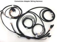
Conversion Adapter Wiring Harness, 85-95 22R-E and 3VZ-E applications
*****NOTICE TO CUSTOMER: If there is a problem suspected with the wiring harness, call ORS. DO NOT cut, alter, or dissect the ORS conversion harness. ORS accepts no responsibility for a harness that has been tampered with.
If wire colors or connections described in these instructions do not match your specific application, please call ORS, we will gladly assist.
-
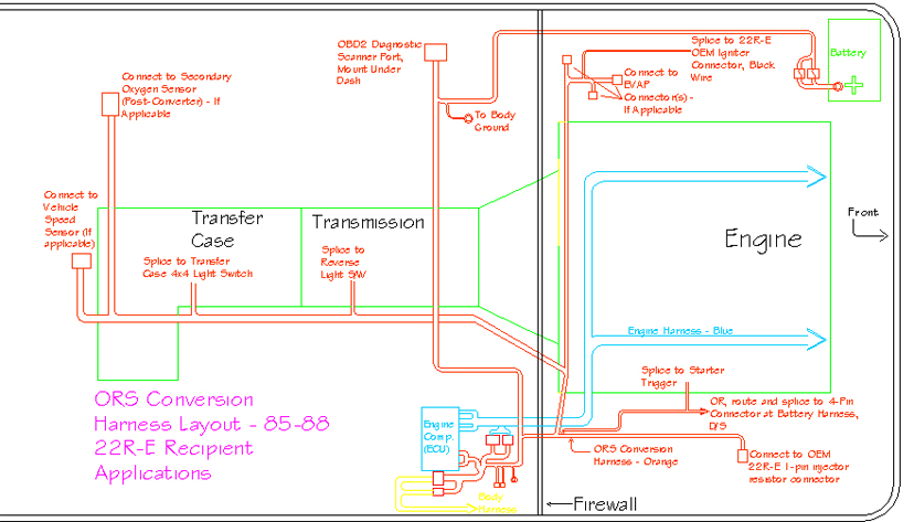
- ORS Conversion Harness Layout – ’85-’88 22R-E Recipient Applications
-
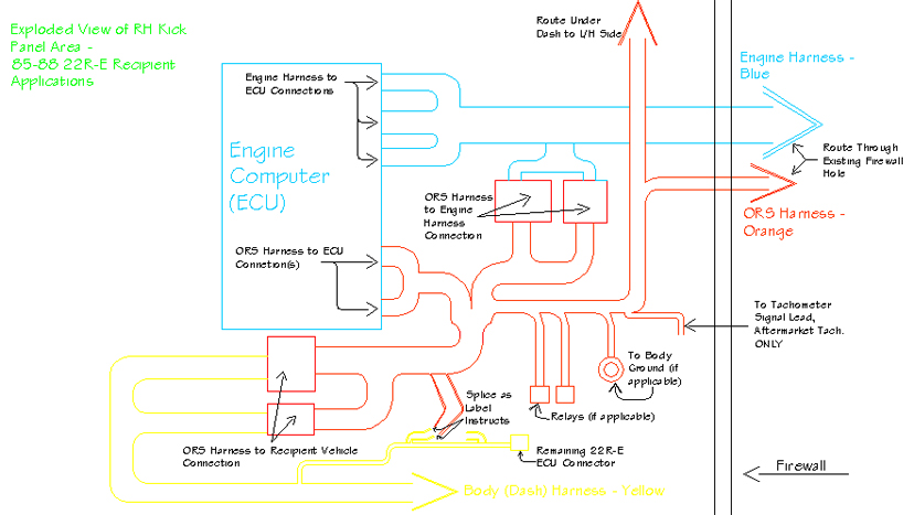
- Exploded View of RH Kick Panel Area – ’85-’88 22R-E Recipient Applications
-
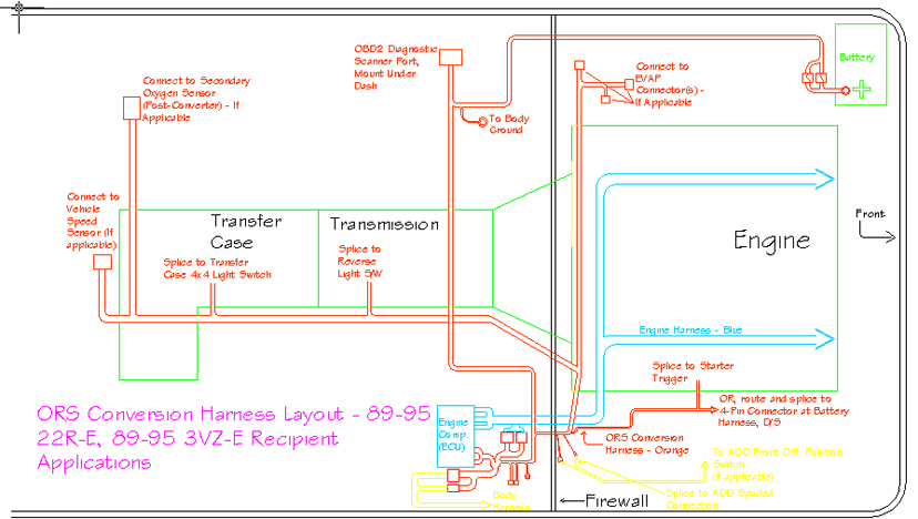
- ORS Conversion Harness Layout – ’89-’95 22R-E, ’89-’95 3VZ-E Recipient Applications
-
- Exploded View of RH Kick Panel Area – ’89-’95 22R-E, ’88-’95 3VZ-E Recipient Applications

- ORS recommends the use of the 3RZ/5VZ battery harness for applications with the battery under the hood. This is the harness that connects the battery terminals to the starter and engine grounds in the donor vehicle. The alternator and starter wiring are also contained in this harness. If this harness is damaged or not available, ORS offers a conversion replacement for this harness, PN ORS-EC046 for 5VZ applications. Install this harness to the engine using the original configuration. Connect the engine ground cable and the starter terminal and cable. Connect the alternator connector and main lead. Route the battery harness underneath the steering shaft and up the driver side fender-well to the battery. Do not connect the battery terminals at this time. If using the ORS 3.4L Battery harness, refer to the provided ORS Battery Harness Installation Notes.
- Be sure the 3.4L/2.7L original engine wiring harness is properly installed on the engine and all connectors are plugged in. Route the engine harness lead behind the alternator and down the LH side of the engine and transmission. We highly recommend wrapping the harness with heat tape or exhaust wrap anywhere the harness passes close to the exhaust.
- Connect the engine harness to the oxygen sensor leads. Depending on your application, there may only be one oxygen sensor connector in the engine harness. If only one is found, the other is contained in the ORS harness and will be connected later.
- Be sure the wiring harness is secured clear of exhaust parts to prevent heat damage.
- Route the engine harness main loom (under hood) toward the RH side. We recommend routing this harness in front of the fuel and brake lines, under the clutch hose and behind the original evaporative canister. The canister firewall mount is a good location to secure this main loom to the firewall using routing clamps.

Engine Harness Routing
- Route the engine wiring harness through the RH side firewall and down to the kick-panel. Connect the ECU connectors to the ECU and lay the ECU in the kick panel area.

Engine Harness Routing
- Lay the ORS conversion harness near the RH kick panel area. Orient the harness so that the leads are pointing in the proper direction.
- Route the diagnostic lead under the dashboard to the LH side of the vehicle. Find a suitable location under the LH dashboard area and mount the diagnostic (OBDII) connector. This connector serves as the port for an OBDII diagnostic scanner.
- Disconnect the fuse holder from the ORS harness. Route the harness end of the ‘battery positive’ lead through the firewall on the LH side. Under the hood, re-connect the fuse-holder. Route and connect this lead to the battery positive terminal. Don’t connect the battery at this time.
- Fasten the lead labeled “body ground” near the diagnostic connector to a suitable body ground location.
- Route all other leads out the firewall into the engine bay (RH side).
- Connect the ORS harness ECU connector(s) to the ECU.
- Connect the ORS harness to the original engine wiring harness (1-3 connectors). Fold/secure the latch on the top of the connector(s), if applicable.
- Connect the ORS harness to the vehicle body wiring harness. These are the white and gray or yellow connectors found in the RH side kick-panel.
- If applicable, for harnesses with leads labeled “to ECU CONN V”: locate the original ECU connector (yellow) still in the vehicle. Cut the appropriate colored wires from this connector and directly splice to the appropriate labeled wires in the ORS harness. Use the wire end that leads into the vehicle’s harness.
- If applicable on AT models: Route the leads labeled “to ECT or A/T ECU connector” to the connector from the original A/T ECU (computer). Splice the leads to the appropriate wires in the A/T ECU connector as labeled, connecting to the wire end that leads into vehicle harness. The original A/T or ECT ECU is not needed and can be discarded.
- The ORS harness contains a lead labeled “tachometer”. If an aftermarket tachometer is used, this lead will provide the necessary RPM signal. If an aftermarket tachometer is not used, cover the end with tape or shrink-wrap and tape this lead to the side of the ORS harness.
- Note: If using the original tachometer, it is already pre-wired in our harness.
- If applicable: The wire in the ORS harness labeled “to + illumination wire” is optional. It allows the ECU to detect electrical loads. Splice this wire into an illumination circuit in the interior, a wire that has 12v with the tail lamps on.
- Route the transfer case (and sometimes reverse light, oxygen sensor, speed sensor) leads (under the hood now) down the RH side of the vehicle. Secure the harness to the firewall/lines/hoses a safe distance from the exhaust.
- MT models: If the ORS harness has 2 wires labeled “reverse light switch”, cut and splice these wires into the reverse light switch on the side of the transmission. This switch is non-directional, meaning each wire has no specific match. If these leads are not on the ORS harness, and the donor vehicle’s transmission is being used, connect the reverse light connector from the 3.4L/2.7L engine harness to the reverse light switch.
- Cut and splice the leads labeled “4WD indicator switch” into the transfer case position switch. This switch is also non-directional. Be sure that all connections are secure and sealed. Also be sure the wiring harness is safely routed under the vehicle.
- If applicable, connect the “speed sensor” connector to the vehicle speed sensor on the rear of the transfer case/transmission.
- If applicable, route the “fuel pump” lead to the fuel pump. Splice to the positive fuel pump wire, leading into the pump. This is usually a blue wire w/ white stripe.
- If applicable, splice/connect the ORS wire labeled “to engine temp. sender for gauge” to the engine’s 1-wire temperature sender/switch. If a 1-wire gauge sender does not exist on engine, install one and connect this wire.
- If applicable, route the EVAP leads (under the hood now) across the firewall to the driver side. Connect to the appropriate evaporative valves and vapor pressure sensor. Use the provided EVAP hose diagram to identify the proper parts.
- The lead labeled “starter” (under the hood) is ultimately connected to the smaller “trigger” terminal on the starter. This can be done one of two ways. 1) If using the 3.4L/2.7L battery harness: route the “starter” lead across the engine bay (in front of radiator), to the battery area. Cut the 4-pin (1-pin on T100 engines) connector from this harness (located near the battery terminals). Splice the wire labeled “starter” to the black wire in this connector. Be sure the connection is secure and sealed. 2) If not using the 3.4L/2.7L battery harness, route the “starter” lead to the starter. Directly connect this lead to the trigger terminal on the starter.
- If applicable, route the lead labeled “injector resistor” out the passenger firewall to the original injector resistor connector on the RH side fender-well. Connect this lead to the original 1-wire connector. Route the lead labeled “to igniter black wire” out the passenger firewall and along the rear of the firewall to the LH side. Splice this lead to the original coil/igniter connector (2-wire green), solid black wire.
- Mount the 5VZ/3RZ ECU. The brackets bolted to the side of the ECU share the same bolt pattern as all Toyota ECU’s. This allows the installer to share brackets from any ECU to help in the mounting process. Find a location near the passenger side kick-panel that will house the ECU. Be sure that the ORS wiring harness and the engine wiring harness leads will reach the ECU and plug in. If the vehicle does not have A/C it is possible to mount the ECU behind the glove box.


ALTERNATOR WIRING
- There are 2 ways to wire the alternator.
FIRST METHOD (RECOMMENDED) - The first method is to connect the original vehicle alternator connector and cable directly to the alternator. In some cases the original vehicle’s alternator connector is a direct plug-in. If the connector is different, the connector from the 5VZ/3RZ alternator can be spliced directly to the original vehicle’s alternator wiring lead. Simply cut the old connector from the lead and splice the 3 wires to the 5VZ/3RZ alternator connector/lead, matching wire colors. The original alternator cable can simply be bolted to the 5VZ/3RZ alternator.
SECOND METHOD - The second method uses the 3.4L/2.7L battery harness to route the alternator circuit beneath the steering shaft with the battery cables. This method is also useful when the original connector does not match the alternator. Locate the vehicle’s original alternator connector.
- Cut the connector from the harness. Read the following instructions to be sure the right length of wire lead is cut.
- If the “starter” lead was spliced into the 3.4L/2.7L battery harness, locate the remaining wires from the 4 wire connector (on the 3.4L battery harness).
- If the starter lead was NOT spliced into the 3.4L/2.7L battery harness, locate the 4 wire connector on the 3.4L battery harness near the battery terminals. Cut the connector from the harness.
- Splice the 3 wires from the original alternator connector to the remaining 3 leads on the battery harness. Be sure to match wire colors! Be sure all connections are sealed and secure. Locate the opposite end of the alternator cable on the battery harness. This cable end terminates near the battery terminals on the battery harness and connected to the fuse box in the donor vehicle.
- Locate the original alternator cable near the original alternator connector.
- Splice these two cables together. Take the time to make a good connection as this is a crucial circuit.
- Connect the alternator connector and cable in the 5VZ/3RZ battery harness to the alternator.
- If the battery is under-hood and re-located to the LH side: Find the power supply wire from the original fuse box, near the original battery location. This wire previously connected to the battery positive terminal. ORS offers an extension cable for this step, ORS-EC047. Using the ORS cable or 8-gauge cable, extend this power lead to reach the new battery location. If not using the ORS lead, be sure to install a fusible link of appropriate size at the end of this cable. Connect this lead to the battery positive terminal.
- Be sure the power supply wire and “starter” leads that were routed in front of the radiator are loomed and properly secured below the radiator support. Excessive contact with the radiator when hot can damage this wiring. Use insulation or further fastening where necessary to prevent contact with the radiator.
- Important: If this step is not performed before engine is started, oil gauge damage may occur. Most 5VZ/3RZ/2UZ/2RZ vehicles come standard with an oil pressure switch to operate a light on the dash. Many older vehicles had a gauge in the instrument cluster, which used an oil sender. If the original vehicle has a gauge, replace the oil switch on the 5VZ/3RZ engine with the oil sender from the original (22R or 3.0L work) engine. It will thread straight in (but may require splicing the old connector to the engine harness). If a new oil sender is needed, Toyota PN 83520-34010 works very well.
- The ORS wiring harness pre-wires the vehicle’s tachometer. However, this tachometer will not work without modification (most cases). We have included an illustration that depicts soldering a 10k ohm resistor to the back of the tachometer. This is done after the instrument cluster has been split open and the tachometer individually removed. This solution was found on internet forums. We suggest searching pirate4x4.com, yotatech.com, or 4x4wire.com for more information on this modification.
- Go through all wiring and be sure that all wires are routed properly and securely fastened. Be sure that all wires are clear of exhaust parts, engine parts, and sharp edges.
Note: In some cases there are two short wires departing the ORS harness labeled “Diagnostic Leads” or “Cruise Control Diagnostic Leads”. These are simply provided in case the need arises to pull trouble codes from the original ABS or Cruise Control systems.
Supplement for Automatic Transmission applications:
When using a late-model floor shifter
- A late model floor-shifter assembly from the donor vehicle can be used with this conversion. The following steps pertain to wiring that shifter.
- If the ORS harness has an ‘original shifter’ connector + a ‘donor shifter’ connector, simply connect the ‘original shifter’ connector to the original shifters connector(s), then connect the ‘donor shifter’ connector to the connection in the donor shifter.
- If the ORS conversion harness contains a lead labeled “to O/D switch”, skip the next step.
- Locate the original connector for the O/D off switch on the center floor-board, near the shifter. The two wire colors necessary are normally yellow-green and white-black. Locate the 2 white wires from the overdrive switch in the new shifter from the donor vehicle. They will be routed from the shifter handle. Connect these wires to the original O/D switch wires. Orientation of these wires does not matter. These can be spliced directly, but we suggest using some sort of connector. Skip the next step
- If the conversion harness contains a lead labeled “to O/D switch”,route this lead under the dashboard to the center floorboard near the shifter. Locate the original connector for the O/D off switch on the center floor-board near the shifter. The two wire colors necessary are normally yellow-green and white-black. Locate the 2 white wires from the overdrive switch in the new shifter from the donor vehicle. They will be routed from the shifter handle. Connect one white wire from the shifter to the ORS conversion harness lead labeled “to O/D switch”. Connect the other white wire to the white-black wire from the original O/D switch, or body ground. The yellow-green wire will be left disconnected. Wrap the end or this wire with tape or simply leave it inside its connector to prevent any possible shorting.
- Locate the original illumination power wires for the shifter assembly, also on the center floorboard, near the previous connector. The wire colors necessary are normally green and white-green or red-black. Locate the 2 white wires that power the shifter assembly illumination in the donor vehicle’s shifter. Connect one white wire to the green wire. Connect the other white wire to the white-green or red-black. Once again, we suggest the use of connectors.
- Note: Starting in 2000, many models used a ‘momentary’ OD Off switch, which is not compatible with the older type switches. If the OD Off function does not work, the use of a ‘momentary’ style switch (matching year/model of the computer) may be required.
89 and Earlier A/T Models:
If the ORS harness contains leads labeled “splice to ECT ECU….”, route these leads to the ECT (transmission) ECU connector, near the shifter. If still in place, remove and discard the ECT ECU. Cut wires from the ECT ECU connector and splice to the ORS harness as labeled.
Instruction Supplement
Installing 5VZ/3RZ A/T Into A43D Vehicles
- Since the original A43D transmission was not electronically controlled, a couple of components were added to the ORS Harness (the ECT switch and the AT temp lamp). Mount the ECT Switch and the AT temp lamp where desired. When the ECT switch is turned on, it will modify the electronic shift pattern to be more aggressive. This is ideal for towing or mountain driving. The AT temp lamp illuminates if the transmission fluid temp reaches a dangerous temperature.
- Due to the column shift setup, the wires in the ORS Harness related to the “O/D Switch” will need to be routed to the steering column area.
- Locate and access the wiring from the original O/D Off Switch (2 wires) on or near the steering column. Cut the yellow/green wire from the original switch. Locate the wire in the ORS Harness labeled “To O/D Off Switch”. Splice the ‘to O/D Off Switch’ wire from the ORS harness into the yellow/green wire leading into the switch.
- Locate the wire in the ORS Harness labeled “to O/D Off Switch Connection, yellow/green wire”. Splice this wire into the other end of the yellow/green wire, leading down into the body wiring.
- Leave the while/black wire intact.
- Note: Starting in 2000, many models used a ‘momentary’ OD Off switch, which is not compatible with the older type switches. If the OD Off function does not work, the use of a ‘momentary’ style switch (matching year/model of the computer) may be required.
A/C on originally equipped A/T models:
*On models equipped originally equipped with the 3.0L engine and an automatic transmission, the A/C contains a relay called the ‘A/C Cut Relay’. This relay is mounted near the heater/evaporator box. It can be accessed by removing the glove box. It is normally labeled ‘cut relay’ or ‘a/c cut relay’. When performing the 3.4L engine swap:
-Remove and discard the A/C Cut Relay
-Install the provided ORS Jumper Connector in place of the relay
This must normally be done before the A/C amplifier will operate the A/C compressor clutch.


